IMT400-09
www.ueonline.com
NOTE: The middle switch assembly is omitted for dual switch controllers.
The outer two switch assemblies are omitted for single switch controllers.
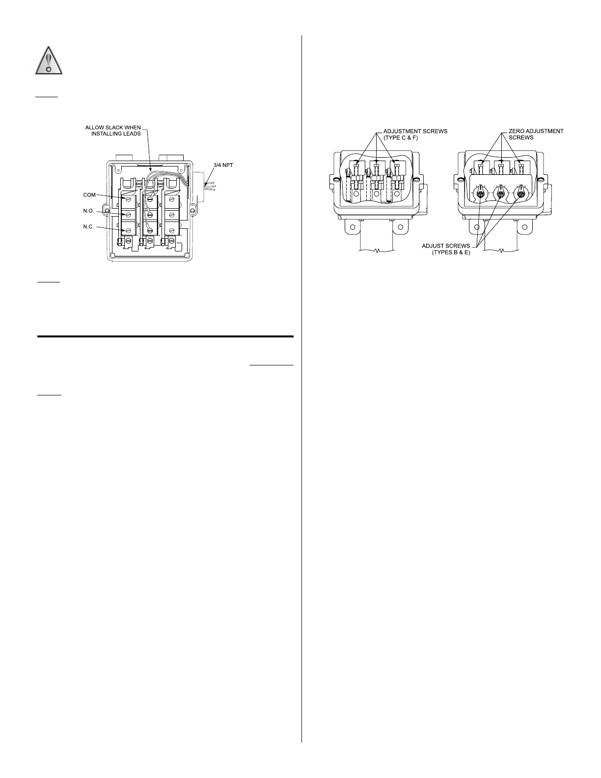
Type “C” and “F” controls have internal hex screw adjustments and type “B”
and “E” have cam assemblies for internal calibrated adjustments, via a refer-
ence dial.
PART II - Adjustments
Tools Needed
Screwdriver
NOTE: For set point adjustments and re-calibration, insert bulb or immersion
stem into a calibrated temperature bath. Allow temperature to stabilize for
10 minutes.
Type C400 & F400
Remove cover. Switch has screw adjustments inside enclosure. If switch
transfer point differs from actual temperature, adjust setting. To RAISE the
temperature setting turn the screw left (clockwise) and to LOWER the setting
turn the screw right (counter clockwise). When making adjustments, do not
exceed the maximum temperature rating on nameplate (see Figure 2).
Types C402, C403, F402 & F403
Remove cover. Follow same procedure as paragraph above. Switches may be
set together or apart, up to 100% of range scales. On dual switch models,
either switch may be set high. On triple switch models, the third (middle)
switch has no over-travel mechanism and must always be set to the highest
temperature when switches are set apart. Altering the setting of one switch
will usually have little effect on the other(s), however re-adjustment may be
desired at a critical temperature setting (see Figure 2).
Types B400, B402, B403, E400, E402 & E403
Controls are factory calibrated for maximum accuracy at the dial midpoint.
Switches may be set together or apart up to 100% of the range scale. On
dual switch models either switch may be set high. On triple switch models, the
third (middle) switch has no over-travel mechanism and must always be set to
the highest temperature when the switches are set apart. Altering the setting of
one switch will usually have little effect on the other(s), however re-calibration
may be desired at a critical setting.
To re-calibrate, turn pointer to desired set point. If the actual temperature
and set point temperature do not agree, turn zero adjustment screw
clockwise to raise and counter clockwise to lower set temperature setting
(See Figure 2)
Figure 1
Re-Calibration Adjustment
Figure 2
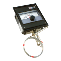
ALLOW ENOUGH SLACK SO AS NOT TO AFFECT SWITCH MOVEMENT
WHEN MAKING SETTING ADJUSTMENTS AND ENSURE THAT THE
WIRES ARE NOT TOUCHING THE COVER WHEN INSTALLED.
NOTE: For larger wire gauges, a one time shift may be experienced or
expected due to space limitations within the enclosure. Verify set point after
installation.
Types With Manual Reset (Option 1530)
These optional models incorporate a snap switch that, when actuated,
remains tripped until temperature decreases and the reset button (located
on top of the control) is manually depressed to the reset position. On multi-
switch units, this switch must be set to the highest setting.
 Loading...