IM800-06
www.ueonline.com
Adjusting Thermometer Type T800
Use the in-process adjustment to check the control. Differences between the
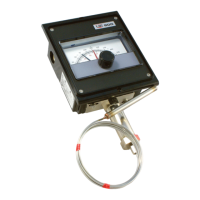
test instrument and the thermometer can be corrected by turning the zero
adjustment “C” per Figure 3 on the thermal assembly. Turning in lowers
indicated reading.
Note: Indicating Pointer Deflection:
The indicating pointers will read slightly low when the bulb temperature is
15° above the controller setting. This deflection is normal and repeatable
(approximately 0.5% of scale range on single switch models) and is due to
the transference of the switching mechanism load to the thermal system. It
can be measured by moving the setting pointer from the high to the low end
of the scale and observing the resultant indicating pointer deflection.
Correction of Capillary
If the length of capillary immersed in the process differs from the amount
immersed at the factory calibration bath, a calibration shift will occur. The
error may be corrected as follows:
Move set pointer to the highest temperature setting. Note indicating scale
reading with the head and sensor at room temperature. Loosen the two
thermal assembly mounting screws. Re-position the housing index against
the calibration on the instrument case (or skeleton casting) at a rate of 1
division line per capillary length listed in the following column. Move to the
left if capillary is to be added to the process, or to the right if capillary is to
be removed from process.
Model Number Range Cap Length/Division*
1 -180 to 120°F 2 ft
2 -125 to 350°F 1 1/2 ft
3 -125 to 500°F 1 ft
4 -40 to 120°F 4 ft
5 -40 to 180°F 3 ft
6 0 to 250°F 2 1/2 ft
7 0 to 400°F 2 ft
8 50 to 650°F 2 ft
* Added to or taken away from the process.
Tighten the two thermal assembly mounting screws. Note change indicated
scale reading (if any).
Turn zero adjustment “C” to bring indicating pointer reading back to the origi-
nal reading noted before. Turning in lowers indicated reading.
Note: The thermal assembly can be returned to its original position by align-
ing its flange with the line scribed on the instrument case.
COMPENSATOR
SWITCH 1
SWITCH 2
Figure 3
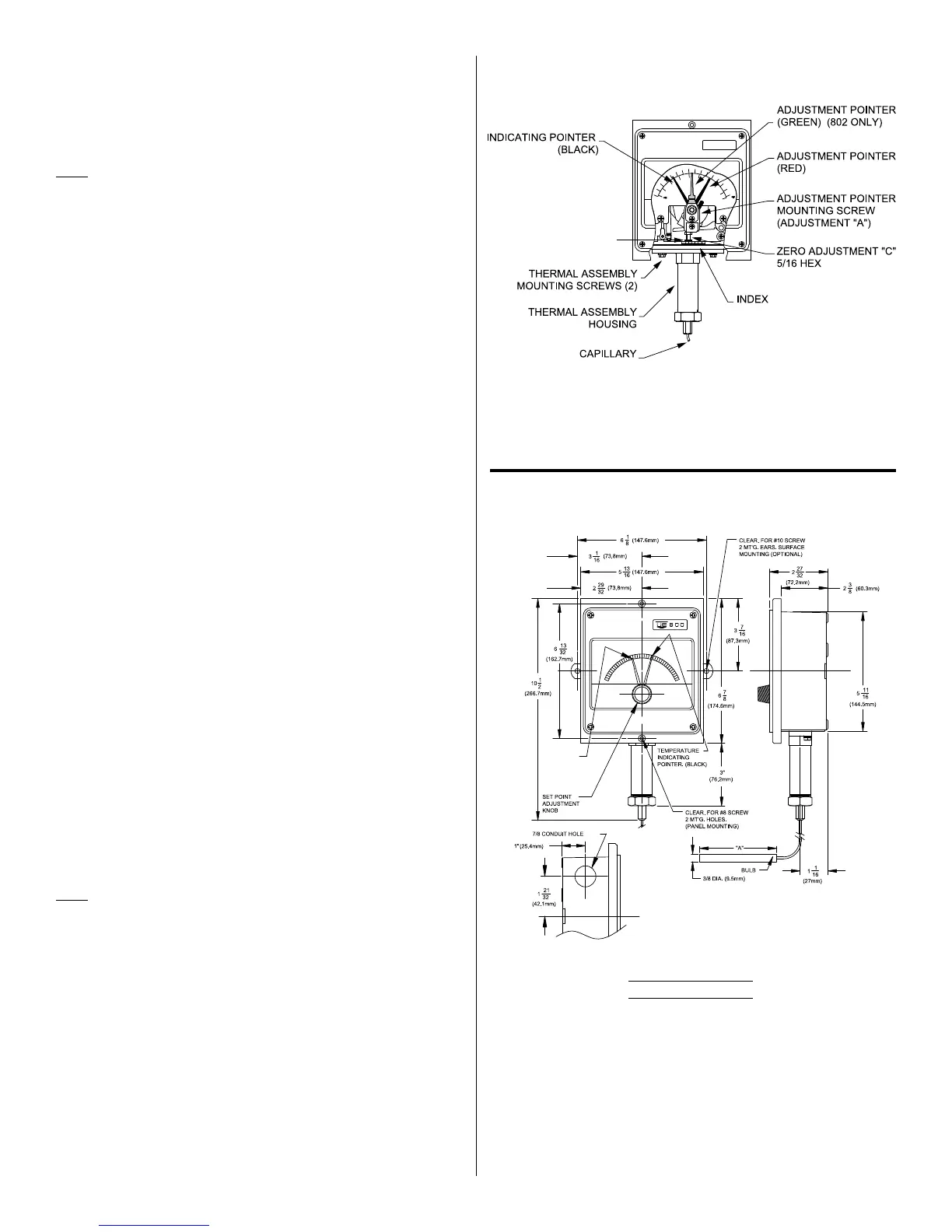
Figure 4
Dimension A
Model Inches mm
1BS 3-3/4 95.3
2BS 2-5/8 66.7
3BS 2-1/8 54.0
4BS 6-3/4 171.5
5BS 5 127.0
6BS 4-1/2 114.3
7BS 3 76.2
8BS 3-1/4 82.6
SET POINT
ADJUSTMENT
POINTER
(RED)
Dimensions
General Layout
 Loading...