Do you have a question about the uher 4000 report IC and is the answer not in the manual?
Describes the drive system of the tape recorder, including motor, flywheel, and drive wheel.
Explains the working principle of the motor, its windings, rotor, and electronic speed control.
Details the electronic components, circuit boards, and their arrangement within the 4000 Report IC.
Describes the electronic system layout for the UHER 4200 and 4400 Report Stereo IC models.
Details the construction and function of the left and right clutches.
Covers pressure roller adjustment and pause control relay testing.
Describes the fast forward and rewind functions and their adjustments.
Information on tape guides and their adjustment.
Covers the alignment of the sound head when disturbed or replaced.
Details checking and adjusting the speed selector and flywheel pressure.
Guides for replacing the motor and various drive belts.
Details on replacing the right and left clutches and their components.
Guide for replacing the drive wheel and spherical bearings, including lubrication.
Provides guidance on proper lubrication of moving parts using sintered metal bearings.
Emphasizes cleanliness of heads, guides, and drive parts for optimal performance.
Details the ON/OFF switch, its function, and adjustment.
Explains motor control contact and battery switch functions and adjustments.
Details the battery cutout switch, its function, and adjustment.
Explains the current limiting contact and its adjustment.
Describes the short-circuit contact K1 and its adjustment.
Guides for checking and adjusting recording/playback switch contacts.
Instructions for checking and adjusting equalizer switch contacts.
Details electrical settings, measured values, and tolerance ranges.
Explains how to measure wow and flutter using a flutter meter.
Procedure for measuring the overall frequency response across tape speeds.
Instructions for measuring the recording equalization at all tape speeds.
Guides for measuring playback equalization at all tape speeds.
Details the procedure for measuring noise voltage according to DIN standards.
| Brand | uher |
|---|---|
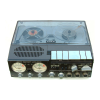
| Model | 4000 report IC |
| Category | Stereo System |
| Language | English |