52
Instructions for the installer
The boilers are specifically produced for the type of gas
requested at the ordination phase.
DANGER!
The transformation of the boiler for the
operation with a type of gas different than
that
specifically requested when the order has
been placed, must be performed by
professionally qualified personnel, in
conformity to the norms and rules in force.
The manufacturer cannot be considered
responsible for any damages consequential
to the transformation not correct or not
performed in conformity with the norms in
force
or instructions given by the manufacturer.
ATTENTION!
After having performed the transformation for
the operation of the boiler with a type of
gas, different (e.g. gas propane) than that
specifically requested at the order stage.
the appliance can work only with such new
type of gas.
ATTENTION!
Indications for appliances working on
Propane
Be sure that, before the installation of boiler,
the reservoir of Propane has been bleeded.
For a correct bleeding of the reservoir revert
to supplier of the gas and, however, to
trained personnel.
If the reservoir has not been properly bleeded
lighting problems can rise.
In such a case revert your self to the supplier
of the reservoir.
For the conversion of the boiler from a gas
to an other one it is necessary to proceed as
follows:
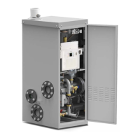
1. Remove the front casing
2. Set the maximum pressure adjusting screw (A.) at
approximately half range and screw of a turn the minimum
pressure adjusting screw (B), as shown on page 50.
3. Try to ignite the boiler: if it fails proceed unscrewing of a
turn the maximum pressure adjusting screw (A) and retry
the ignition. Repeat more times the operation, till the ignition
of the boiler.
4. Adjust the CO
2
value according to the type of gas as
described in the paragraph “3.24 - Adjustment of the
burner.”
3.26 - ADAPTATION FOR THE USE OF OTHER GASES
3.25 - VARIATION OF OUTPUT RANGE
It is possible to adjust the maximum input by
reducing the fan speed.
Modify the parameter FH from the boiler panel
board:
Factory parameter (access code)
For example: ALKON 50 with parameter FH set on 72 (G 20)
the correspondent maximum input will be of 34,8 kW.
For example: ALKON 70 with parameter FH set on 76 (G 20)
the correspondent maximum input will be of 50 kW.
Maximum imput (kW)
0
10
20
30
40
50
60
70
Output range
ALKON
R 50
80
90
100
ALKON
R 70
0 5 10 15 20
25 30 35 40 45 50 55 60 65
70
Parameter FH

 Loading...