3
1
2
3
4
5
6
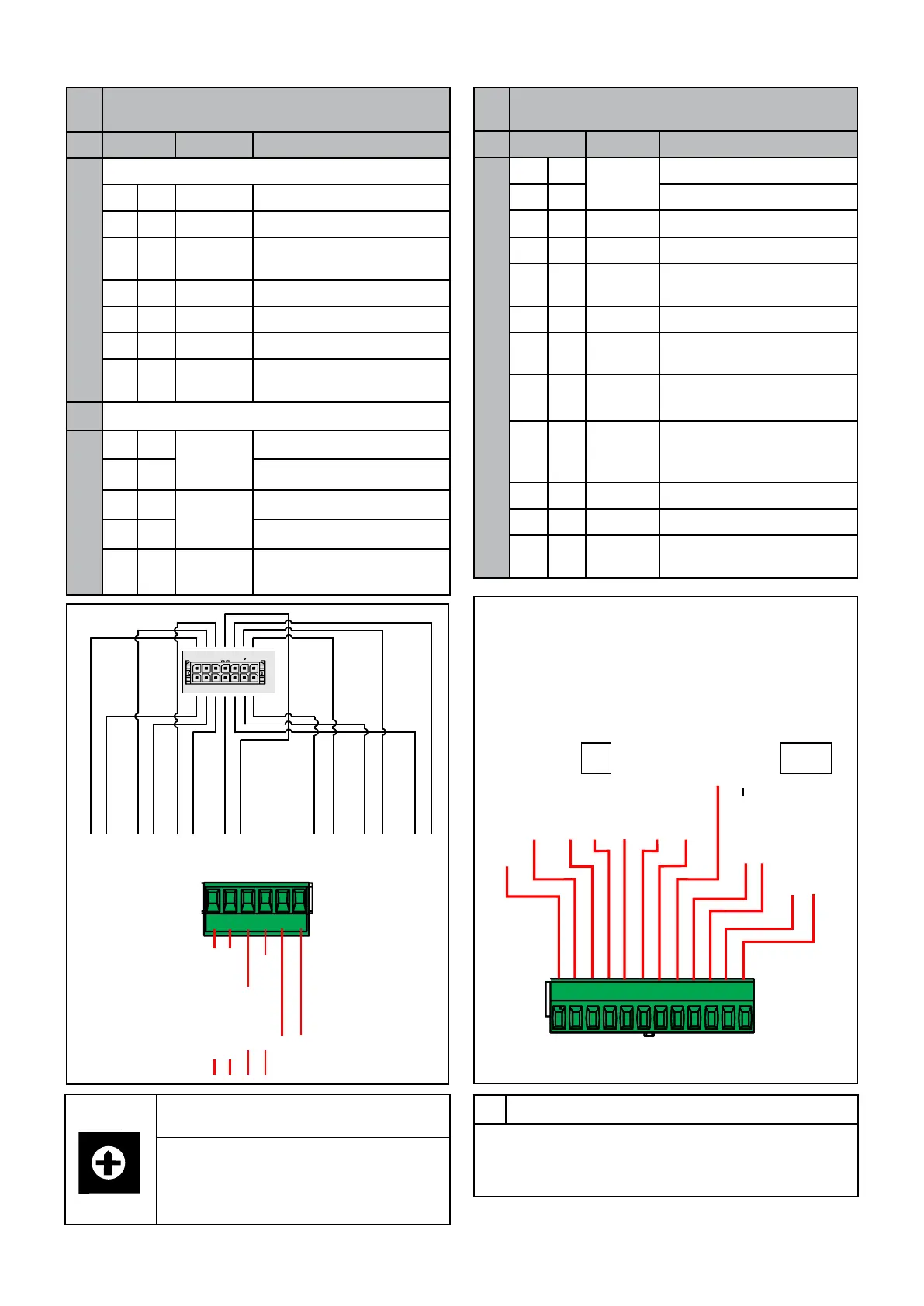
Y1
ALIM. + 24 V
eBUS
+
ALIM. - GND
eBUS
-
GND
981011121314
SL
3
10
8
2
9
1
PF
11
4
2134567
A1
PF
min.
PG
min.
DK
12
5
13
6
SRG
14
7
SMG
INGR ANALOG.
Modbus A
0-10V
GND 0-10V - INGR.
Stemp. ACC
Config.
FL
C.P
12 11 10 98 765
4321
Modbus B
PLC
eBUS
eBUS +
INAIL
INGR. COM (9 ÷ 11)
TA
0
1
2
3
4
5
6
7
8
9
Sw1
SW1
Bus 0-9 addresses selector.
Usually positioned on 0 for external
BCM (cascade controller).
With internal BCM (cascade boiler), it
assumes other values.
POW.SUPP. + 24 V
POW.SUPP. - GND
COM INPUT (9 ÷ 11)
ANAL. INPUT
GND 0-10V INPUT
6 HOST CONNECTORS
to manage the system remotely
No.
Pin S.E. Description
Y2
1
Modbus
A (PLC)
2
B (PLC)
3
eBUS + Est. Cascade Regulator
4
eBUS - GND
5
4 0-10V
C.P.M.
Modulating Pump
Control
6
GND - 0-10 V
7
6 Analogue input
0 - 10 V (*) / SE
8
4 Stemp.
ACC
Storage tank
temperature sensor
9
12 Cong Programmable digital
input:
Generator enabling
10
12 FL Flow switch
11
12 INAIL Safety input (nc)
12
Common Inputs 9 ÷ 11
5 LOCAL CONNECTORS
to manage the boiler/cascade
No.
Pin S.E. Description
A1
Internal boiler connections
7
14 SMG
Global ow sensor
6
13 SRG
Global return sensor
5 12 DK Water deciency safety
pressure switch
4 11 PG min. Min Gas pressure switch
3 10 SL Level sensor
2 9 PF Flue gas pressure switch
1 8 PF min Smoke pressure mini-
mum pressure switch
Y1 Generators cascade connections
1 +
Input
Pow. Supp. 20 ÷ 40 Vdc
2 - GND
3 +
eBUS
4 - GND
5 6 SMG Global ow sensor (du-
plicate).
(*) ANALOGUE INPUT
Normally it is congured for control via SE (external
sensor) if the 0-10 V input is used, congure as
indicated in chap.3.3).
 Loading...