4.6 Recommended practices
Below, recommendations are given for a number of common network situations.
4.6.1 Impedance grounded 3-wire systems
Typical examples: MV distribution networks in a 3-phase, 3-wire network without neutral conductor
impedance grounding (Petersen coil with/without resistor) is common. Figure 28 shows the
secondary side of the transformer and the grounding impedance.
When an earth fault occurs the transformer neutral point voltage U
n
rises. Measuring this voltage is a
good indicator of earth faults and can be used to track them.
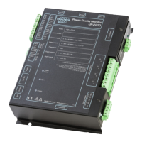
Connect your UP-2210 to measure line-to-line voltages U1-U3 and phase currents I1-I3 according
to one of the sections 4.4.3, 4.4.4, 4.4.5, and 4.4.6 depending on how many PT/CT there are.
Connect channel U4 to measure the transformer neutral point voltage U
n
.
Channel I4 is normally not used. Connect it to ground.
4.6.2 Effectively (directly) grounded 3-wire systems
Typical examples: HV distribution and transmission networks.
HV networks are 3-phase, 3-wire networks without neutral conductor. Direct grounding is common
here.
Connect your UP-2210 to measure line-line voltages U1-U3 and phase currents I1-I3 according to
one of the sections 4.4.3, 4.4.4, 4.4.5 and 4.4.6 depending on how many PT/CT there are.
Channels U4 and I4 are normally not used. Connect them to ground.

 Loading...