Page
7
SunFrame
Unirac Code-Compliant Installation Manual
R
1411 Broadway Boulevard NE
Albuquerque NM 87102-1545 USA
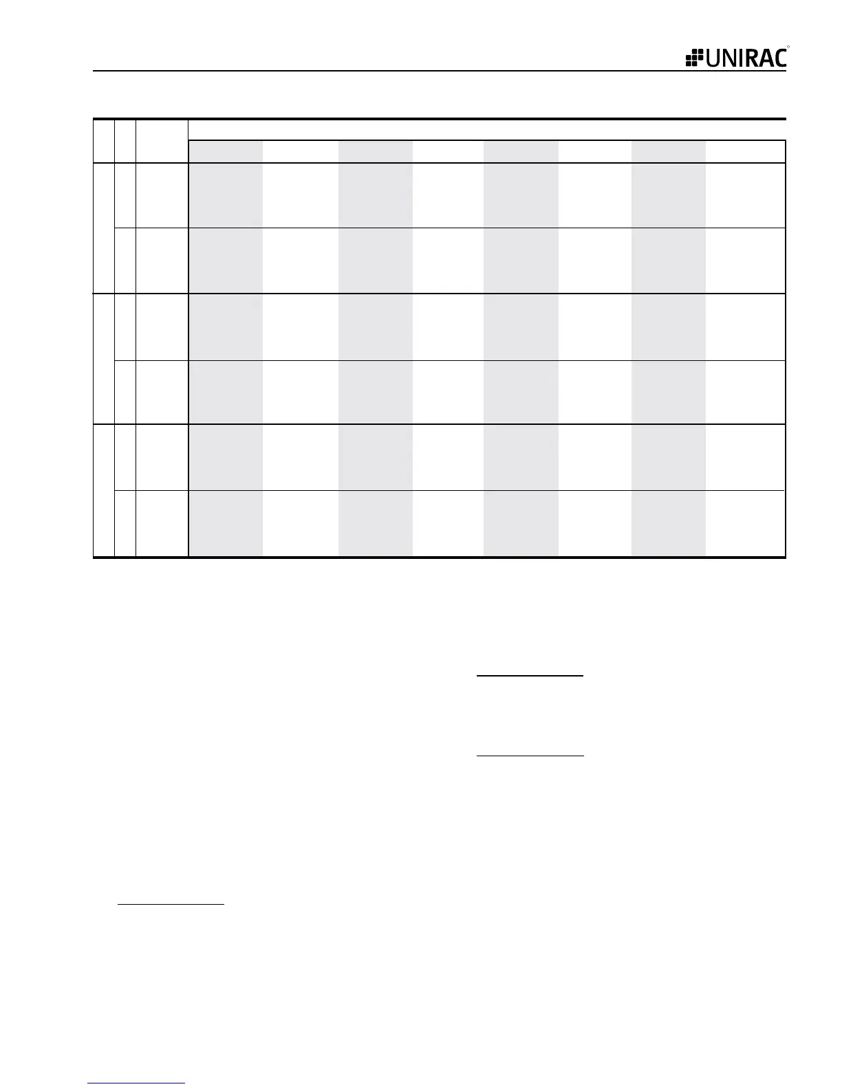
2 10 -21.0 -25.9 -31.4 -37.3 -43.8 -50.8 -58.3 -74.9
2 20 -20.6 -25.5 -30.8 -36.7 -43.0 -49.9 -57.3 -73.6
2 50 -20.1 -24.9 -30.1 -35.8 -42.0 -48.7 -55.9 -71.8
2 100 -19.8 -24.4 -29.5 -35.1 -41.2 -47.8 -54.9 -70.5
3 10 -34.6 -42.7 -51.6 -61.5 -72.1 -83.7 -96.0 -123.4
3 20 -27.1 -33.5 -40.5 -48.3 -56.6 -65.7 -75.4 -96.8
3 50 -17.3 -21.4 -25.9 -30.8 -36.1 -41.9 -48.1 -61.8
3 100 -10.0 -12.2 -14.8 -17.6 -20.6 -23.9 -27.4 -35.2
2 10 -27.2 -33.5 -40.6 -48.3 -56.7 -65.7 -75.5 -96.9
2 20 -27.2 -33.5 -40.6 -48.3 -56.7 -65.7 -75.5 -96.9
2 50 -27.2 -33.5 -40.6 -48.3 -56.7 -65.7 -75.5 -96.9
2 100 -27.2 -33.5 -40.6 -48.3 -56.7 -65.7 -75.5 -96.9
3 10 -45.7 -56.4 -68.3 -81.2 -95.3 -110.6 -126.9 -163.0
3 20 -41.2 -50.9 -61.6 -73.3 -86.0 -99.8 -114.5 -147.1
3 50 -35.3 -43.6 -52.8 -62.8 -73.7 -85.5 -98.1 -126.1
3 100 -30.9 -38.1 -46.1 -54.9 -64.4 -74.7 -85.8 -110.1
2 10 -24.7 -30.5 -36.9 -43.9 -51.5 -59.8 -68.6 -88.1
2 20 -24.0 -29.6 -35.8 -42.6 -50.0 -58.0 -66.5 -85.5
2 50 -23.0 -28.4 -34.3 -40.8 -47.9 -55.6 -63.8 -82.0
2 100 -22.2 -27.4 -33.2 -39.5 -46.4 -53.8 -61.7 -79.3
3 10 -24.7 -30.5 -36.9 -43.9 -51.5 -59.8 -68.6 -88.1
3 20 -24.0 -29.6 -35.8 -42.6 -50.0 -58.0 -66.5 -85.5
3 50 -23.0 -28.4 -34.3 -40.8 -47.9 -55.6 -63.8 -82.0
3 100 -22.2 -27.4 -33.2 -39.5 -46.4 -53.8 -61.7 -79.3
90 100 110 120 130 140 150 170
Table 3. p
net30
(psf) Roof Overhang
Source: ASCE/SEI 7-05, Minimum Design Loads for Buildings and Other Structures, Chapter 6, p. 44.
Roof 27 to 45 degrees Roof 7 to 27 degrees Roof 0 to 7 degrees
Basic Wind Speed, V (mph)
Effective
Wind Area
(sf)Zone
Step 5: Determine the Topographic Factor, K
zt
:
For the purposes of this code compliance document, the
Topographic Factor, K
zt
, is taken as equal to one (1), meaning,
the installation is on level ground (less than 10% slope). If the
installation is not on level ground, please consult ASCE 7-05,
Section 6.5.7 and the local building authority to determine the
Topographic Factor.
Step 6: Determine Exposure Category (B, C, D):
Determine the Exposure Category by using the following
definitions for Surface Roughness Categories.
The ASCE/SEI 7-05* defines wind exposure categories as
follows:
Surface roughneSS b is urban and suburban areas,
wooded areas, or other terrain with numerous closely
spaced obstructions having the size of single family
dwellings.
Surface roughneSS c has open terrain with scat-
tered obstructions having heights generally less than
30 feet. This category includes flat open country,
grasslands, and all water surfaces in hurricane prone
regions.
Surface roughneSS d has flat, unobstructed areas
and water surfaces outside hurricane prone regions.
This category includes smooth mud flats, salt flats, and
unbroken ice.
Also see ASCE 7-05 pages 287-291 for further explanation and
explanatory photographs, and confirm your selection with the
local building authority.
 Loading...