P O R T A L T I +
Portal Installation Manual 19
Document #: PTL1001
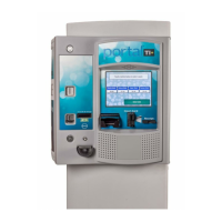
Figure 14. Inside the AC Connector
5. Remove the screw holding the stabilizer plate in place and set both aside until after
you have finished securing the wires.
6. Thread the power wires through the strain relief.
7. Remove the white stabilizer plate.
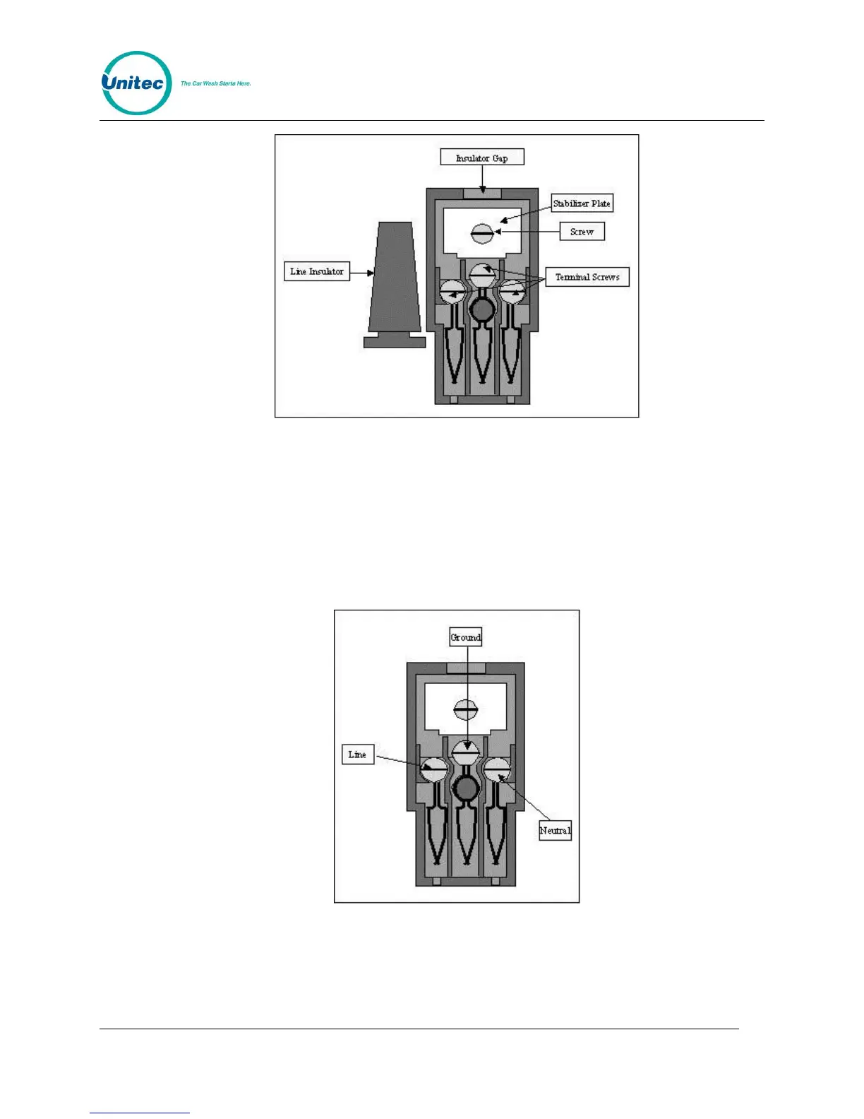
8. Secure the Line (Black), Neutral (White) and Ground (Green) wires to the appropriate
terminal screws. (See Figure 23). Re-tighten the screws to hold the wires in place.
Figure 15. Line - Neutral - Ground Connections
9. Re-assemble the AC connector and insert it into the power inlet. Use wire ties to
route and secure the extra cable.
 Loading...