16
Please contact Universal
®
Gym Equipment/FFA Corp. for missing or defective parts at one of the following: Phone 1-800-
472-9856 or Fax 1-662-495-5038 or E-mail at customerservice@universalgymequipment.com.
Mailing address: Universal
®
Gym Equipment/FFA Corp. - 100 Tubb Ave. West Point, MS 39773.
Website www.universalgymequipment.com
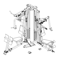
FIGURE 6
Step 48.
Step 49.
Step 50.
Step 51.
Step 52.
Step 53.
Step 54.
Step 55.
Step 56.
Step 57.
Step 58.
Step 59.
Step 60.
Step 61.
Step 62.
Step 63.
Push 50mm x 75mm END CAPS (67) over ends of EXTENSION BASE (12).
Attach LOWER PULLEY BRACKET (29) to EXTENSION BASE (12) with 3/8” x 3” HEX HEAD BOLTS (88), 3/8”
WASHERS (100) and 3/8” NYLON NUTS (104).
Attach EXTENSION BASE (12) to PRESS BASE FRAME (2) with 1/2” x 3-1/2” HEX HEAD BOLTS (85), 1/2” WASH-
ERS (99), LINK PLATE (32) and 1/2” NYLON NUTS (103).
Push 50mm x 75mm END PLUGS (68) into ends of LEG PRESS (7).
Attach one BEARING HOUSING (41) to PRESS BASE FRAME (2) with 1/2” x 1-3/4” HEX HEAD BOLTS (87), 1/2”
WASHERS (99) and 1/2” NYLON NUTS (103). See DETAIL.
Insert axle of LEG PRESS (7) into mounted BEARING HOUSING (41). Slide other BEARING HOUSING onto axle
and attach to PRESS BASE FRAME (2) with 1/2” x 1-3/4” HEX HEAD BOLTS (87), 1/2” WASHERS (99) and 1/2”
NYLON NUTS (103).
Using an allen wrench, tighten SET SCREWS in both BEARING HOUSINGS (41).
Push 25mm x 50mm END PLUG (69) into SEAT ARM (21).
Attach SEAT PAD (58) to SEAT ARM (21) with 3/8” x 1-3/4” HEX HEAD BOLT (92) and 3/8” WASHERS (100).
Attach ADJUSTABLE SEAT TUBE (23) to SEAT ARM (21) with 3/8” x 3” HEX HEAD BOLT (88), 3/8” WASHERS
(100) and 3/8” NYLON NUTS (104).
Pull out on SPRING KNOB (78), insert ADJUSTABLE SEAT TUBE (23) and release SPRING KNOB at desired
height to lock in place.
Attach BACK SUPPORT (26) to PRESS UPRIGHT (4) with 1/2” x 3” HEX HEAD BOLTS (86),1/2” WASHERS (99)
and 1/2” NYLON NUTS (103).
Push 45mm SQUARE PLUG (71) into end of ADJUSTABLE BACK ARM (20).
Thread SPRING KNOB (78) into PRESS BASE FRAME (1) and BACK SUPPORT (26).
Attach BACK PAD (57) to ADJUSTABLE BACK ARM (20) with 3/8” x 1” HEX HEAD BOLTS (93) and 3/8” WASH-
ERS (100).
Pull out on SPRING KNOB (78) in BACK SUPPORT (26) and insert ADJUSTABLE BACK ARM (20) into BACK
SUPPORT and release SPRING KNOB at desired position to lock in place.
IMPORTANT: The BEARING HOUSINGS (41) have SET SCREWS on one side. The BEARING
HOUSINGS must be mounted with the SET SCREWS on the outside as shown in DETAIL.
 Loading...