7
Please contact Universal
®
Gym Equipment/FFA Corp. for missing or defective parts at one of the following: Phone 1-800-
472-9856 or Fax 1-662-495-5038 or E-mail at customerservice@universalgymequipment.com. Mailing
address: Universal
®
Gym Equipment/FFA Corp. - 100 Tubb Ave. West Point, MS 39773.
Website www.universalgymequipment.com
IMPORTANT
PLEASE READ ALL INSTRUCTIONS CAREFULLY BEFORE ASSEMBLING
FIGURE 1
Step 1.
Step 2.
Step 3.
Step 4.
Step 5.
Step 6.
Step 7.
Push 50mm x 75mm END PLUGS (51) into ends of TOP FRAME (3), REAR UPRIGHT (4), WEIGHT BASE (6) and
REAR STABILIZER (10).
Attach REAR UPRIGHT (4) and WEIGHT BASE (6) to REAR STABILIZER (10) with 1/2” x 3-1/2” HEX HEAD BOLTS
(65), 1/2” WASHERS (82) and 1/2” NYLON NUTS (85).
Attach BASE FRAME (1) to WEIGHT BASE (6) with 1/2” WASHERS (82) and 1/2” NYLON NUTS (85).
Push two PLASTIC GUIDE ROD HOLDERS (56) into outer holes in WEIGHT BASE (6) and WEIGHT FRAME (5).
Slide a RUBBER DOUGHNUT (48) about 3” onto one end of each GUIDE ROD (27) and insert into WEIGHT BASE (6).
Slide the WEIGHTS (30), one at a time, down the GUIDE RODS (27).
Insert the SELECTOR ROD (22) through the center hole of the TOP WEIGHT (31) and fasten through top hole of
SELECTOR ROD with TOP PLATE BOLT (62).
IMPORTANT: Loading the WEIGHT PLATES (30) will require two people. One to hold the GUIDE RODS (27)
steady while the other person slides the WEIGHT PLATES down the GUIDE RODS.
Step 8.
Step 9.
Step 10.
Step 11.
Step 12.
Step 13.
Step 14.
Step 15.
Slide TOP WEIGHT (31) down GUIDE RODS (27) and insert SE-
LECTOR PIN (22) through desired WEIGHT (30) and SELECTOR
ROD (22).
Slide WEIGHT FRAME (5) down onto GUIDE RODS (27) and at-
tach to REAR UPRIGHT (4) with 1/2” x 3-1/2” HEX HEAD BOLTS
(65), 1/2” WASHERS (82) and 1/2” NYLON NUTS (85).
Attach FRONT UPRIGHT (2) to BASE FRAME (1) at two loca-
tions. Fasten at upper location with 1/2” x 4-1/4” HEX HEAD BOLTS
(64), 1/2” WASHERS (82) and 1/2” NYLON NUTS (85). Fasten at
lower location with 3/8” x 3” HEX HEAD BOLTS (70), 3/8” WASH-
ERS (83) and 3/8” NYLON NUTS (86).
Attach TOP FRAME (3) to WEIGHT FRAME (5) with 1/2” WASH-
ERS (82) and 1/2” NYLON NUTS (85).
Attach TOP FRAME (3) to FRONT SUPPORT (2) with 1/2” x 4-1/
4” HEX HEAD BOLTS (64), 1/2” WASHERS (82) and 1/2” NYLON
NUTS (85).
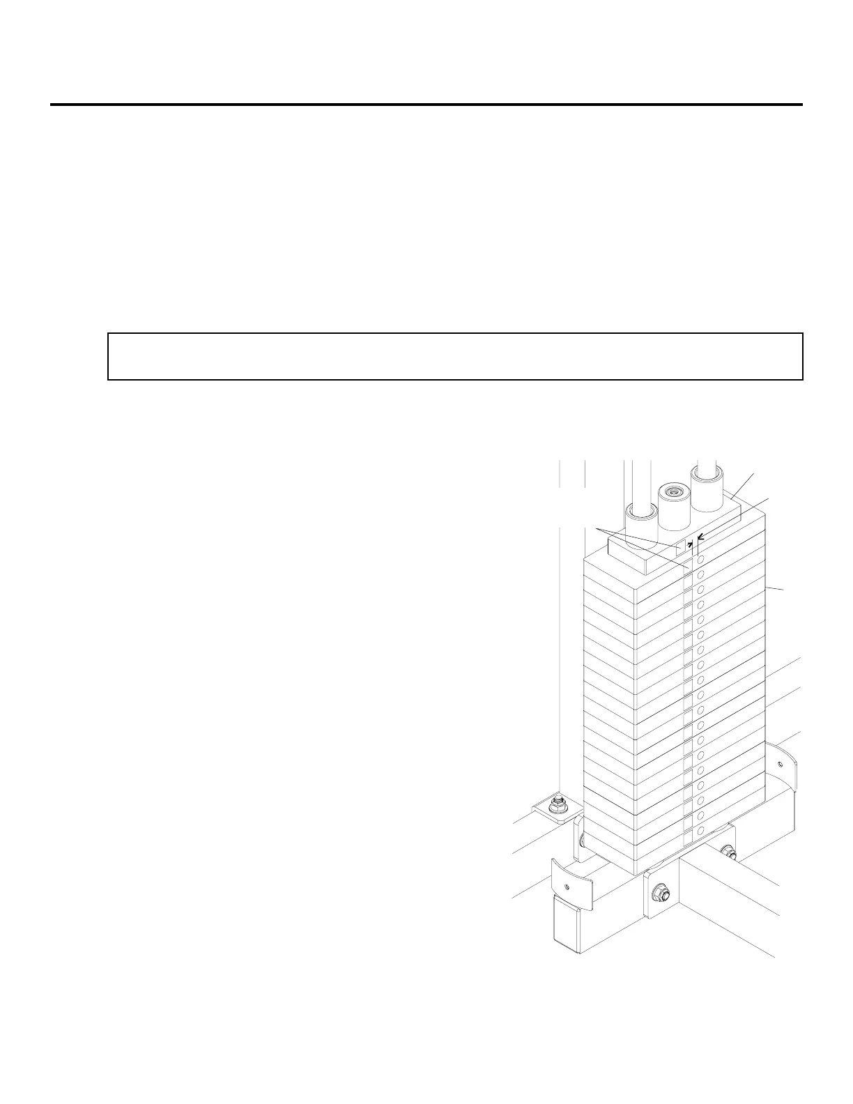
FIGURE 1 DETAIL
Peal backing from WEIGHT LABEL “2” and apply to first WEIGHT
PLATE (30) 1/2” to left of hole as shown.
Peal backing from WEIGHT LABEL “1” and apply to TOP PLATE
(31) directly above WEIGHT LABEL “2” as shown.
Continue appling WEIGHT LABELS “3” through “19” to WEIGHT
PLATES (30) 1/2” to left of hole as shown.
FIGURE 1 DETAIL
31
30
1/2”
WEIGHT
LABELS
 Loading...