ZoneContr
olModule_IS_12-06, Copyright © 2006 Uponor, Printed in the United States
Wiring Instructions
Refer to the following instructions to
properly wire the module.
1. Strip
3
⁄8" insulation from the wire.
2. Ensure the wire is fully seated in
t
he terminal and that it does not
s
hort to adjacent wires.
3. Twist loose stranded wire tightly.
Ensure no loose strands are present.
4. Tighten the terminal nut.
Note: Each terminal is equipped with
a jamb plate for accommodating
s
tranded wire. When reconnecting
the terminal, it may be
n
ecessary to push the jamb
p
late back into place with a
suitable round punch prior to
reinserting the stranded wires.
The maximum number of
connections per terminal is four.
If more than four wires are
r
equired at the terminal, bundle
o
r wire nut the wires together
a
nd run one wire to the terminal.
N
ote:
I
f using Uponor 500 Series
c
ontrols, use a minimum of
t
hree-wire thermostat wire
for proper functioning of
the thermostat. (Five wire
is recommended.)
Fuse Replacement
Replace fuses on the board following
the guidelines below.
• 2A fuse for 50VA transformer
• 3A fuse for 75VA transformer
• 4A fuse for 100VA transformer
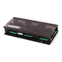
Figure 1: Module Jumper
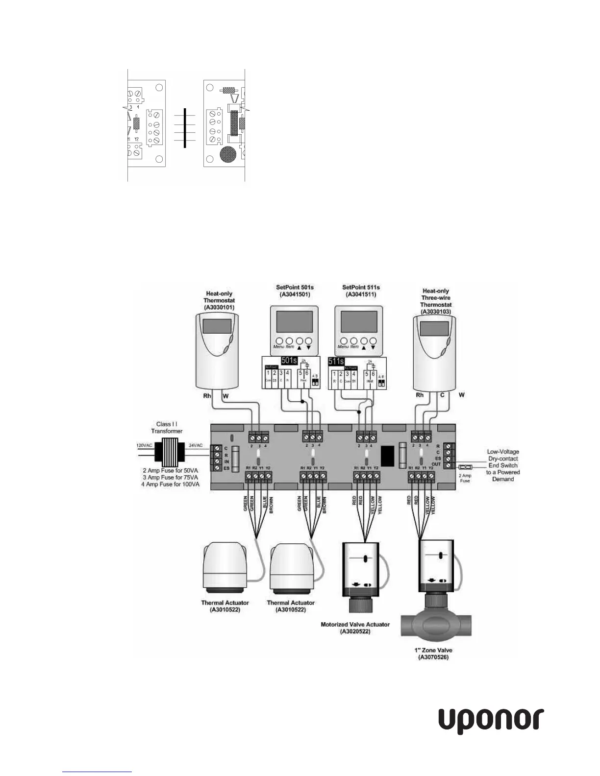
Figur
e 2: Wiring Diagr
am
Uponor, Inc. Tel:
(
800
)
321-4739
5925 148th Street West Fax:
(
952
)
891-1409
A
pple
V
alley
, MN 55
124
W
eb
:
w
w
w.uponor-usa.com
 Loading...