15
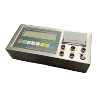
CONNECTORS
Connecting load cells to the indicator
QUICK DISCONNECT AS SHOWN BELOW:
The number of weighing pads and load cells corresponds to the weighing modes. If the
pads or load cells are not connected properly the indicator will not function properly.
Please use the following table to connect your pads correctly.
INNER TERMINAL BLOCK CONNECTION DIAGRAM
Weighing Pad # Load Cell Connection Weighing Mode
1 LFW [Mode 1] Setting “1”
2 LFW, RFW [Mode 2] Setting “2”
3 LFW, LRW, RRW [Mode 3] Setting “3”
4 LFW, RFW, LRW, RRW [Mode 4] Setting “4”
DB9 Connection (9 pin Serial Connector)
RS232: DB9 SERIAL CONNECTOR PINOUT
Pin function and denition are bellow:
DB9 Pin Denition Function
2 TXT Transmit Data
3 RXD Receive Data
5 GND Ground Interface
● US-M5 can connect with 4 weighing pads or 24 pcs of load cells of 350Ω at most
 Loading...