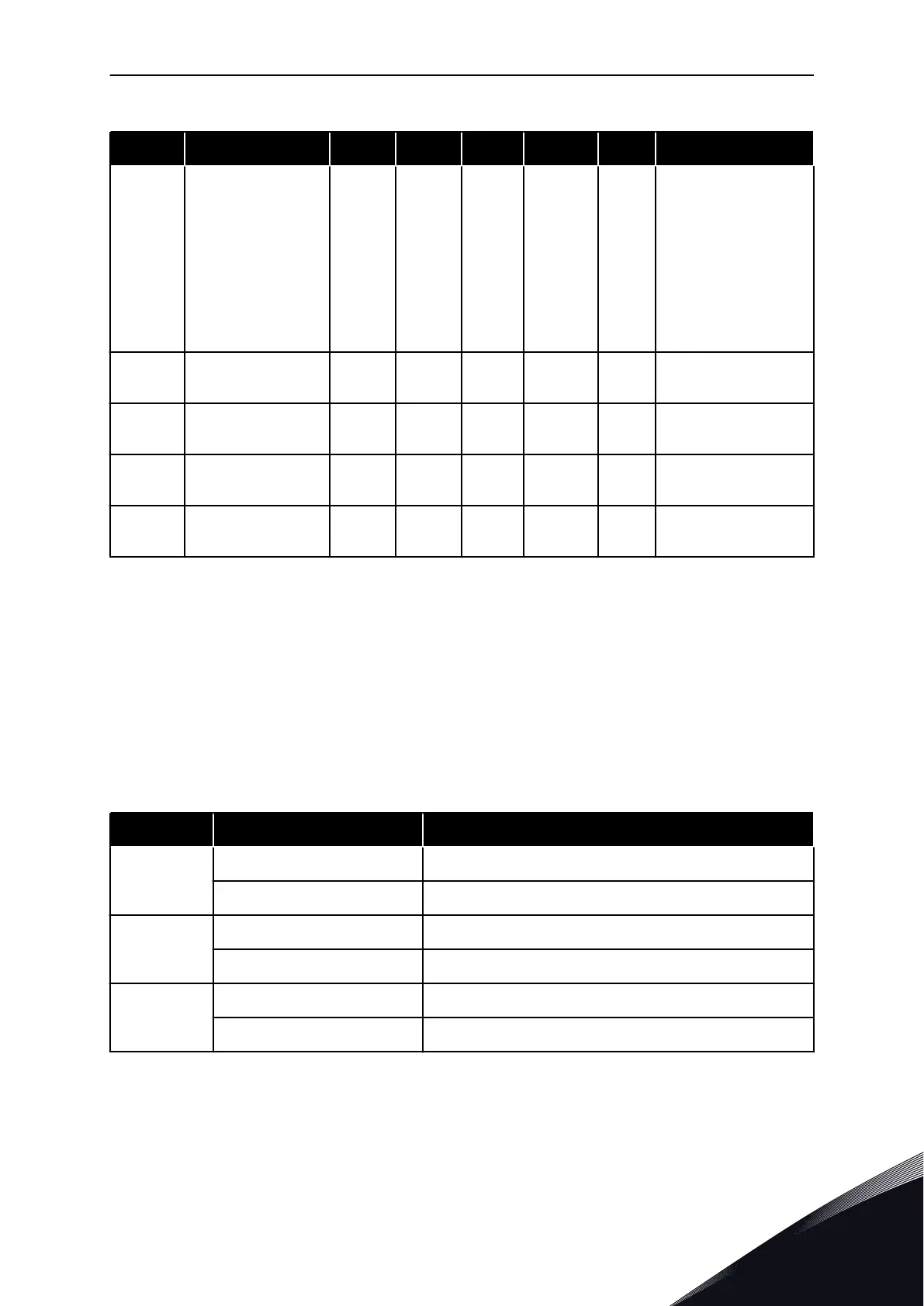
Table 108: The basic I/O parameters in the I/O and Hardware menu
Index Parameter Min Max Unit Default ID Description
V5.1.11
Analogue Output 1
Mode
1 3 1 2512
Shows the mode that is
set for the analogue
input signal. The selec-
tion is made with a DIP
switch on the control
board.
1 = 0...20mA
3 = 0...10V
V5.1.12 Analogue Output 1 0 100 % 0.00 2513
Status of the analogue
output signal
V5.1.13 Relay Output 1 0 1 0 2514
Status of the relay out-
put signal
V5.1.14 Relay Output 2 0 1 0 2515
Status of the relay out-
put signal
V5.1.15 Relay Output 3 0 1 0 2516
Status of the relay out-
put signal
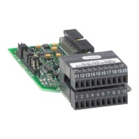
7.2 OPTION BOARD SLOTS
The parameters in this menu are different for all the option boards. You see the parameters
of the option board that you installed. If there is no option board in the slots C, D or E, you do
not see parameters. See more about the location of the slots in Chapter 10.6.1 Programming
of digital and analogue inputs.
When you remove an option board, the fault code 39 and the fault name Device removed show
on the display. See Chapter 11.3 Fault codes.
Table 109: Option board related parameters
Menu Function Description
Slot C
Settings The settings that are related to the option board
Monitoring Monitor the data that is related to the option board
Slot D
Settings The settings that are related to the option board
Monitoring Monitor the data that is related to the option board
Slot E
Settings The settings that are related to the option board
Monitoring Monitor the data that is related to the option board
I/O AND HARDWARE MENU VACON · 193
LOCAL CONTACTS: HTTP://DRIVES.DANFOSS.COM/DANFOSS-DRIVES/LOCAL-CONTACTS/
7

 Loading...