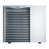
Do you have a question about the Vaillant aroTHERM VWL ../2 A 230 V series and is the answer not in the manual?
| Type | Air-to-water heat pump |
|---|---|
| Power Supply | 230 V |
| GWP (Global Warming Potential) | 3 |
| Refrigerant | R290 (propane) |
| Operating temperature range | -20 °C to +35 °C |
Classifies warnings by severity using symbols and signal words for Danger, Warning, and Caution.
Outlines work requiring qualified persons and adherence to technology and regulations.
Covers dangers from improper operation, electric shock, safety devices, and scalding.
Emphasizes observing national regulations, standards, guidelines, and laws.
Indicates compliance with directives and lists product testing approvals.
Places responsibilities on manufacturers/installers for correct equipment, installation, and servicing.
Details statutory requirements, standards, and reminders of regulatory acts.
Covers control of hazardous substances and refrigerant regulations.
Defines the heat pump's proper application as an air/water system for domestic heating.
Emphasizes observing operating and installation instructions for system components.
Instructs to pass instructions and documents to the system operator.
Lists type designations and article numbers for which instructions apply.
Mentions product can work at specific outside temperatures and lists safety functions.
Lists components: heat pump, control module, hydraulics, system controller.
Explains the product's circuits, heating mode, and thawing process.
Explains operation outside limits results in unit shutdown by control and safety devices.
Provides schematic diagrams for various VWL models, listing numbered components.
Indicates that type designation and serial number are found on the identification plate.
Details meanings of various labels and codes found on the product's identification plate.
Covers delivery, transport, positioning, and unpacking the product safely.
Details safe methods for transporting the product, including warnings about lifting and tilting.
Provides steps for safely unpacking the product, with warnings about lifting heavy weights.
Lists items to check in the packaging units: condensate discharge, seals, feet, hose.
Specifies required clearances for installation and unit dimensions.
Provides dimensions and connection details for the units.
Specifies required clearances (A, B, C, D, E) for heating mode installation, with cautions.
Provides guidance on choosing an installation site, considering regulations, noise, and avoiding specific locations.
Details installing the unit on supports, ensuring no water collects underneath, and preventing ice formation.
Explains how to prepare the condensate discharge, with warnings about frozen condensate and ice buildup.
Covers removing side casing, aligning product, and hydraulics installation.
Provides step-by-step instructions for removing the side casing.
Explains how to align the product horizontally for condensate flow using vibration-damping feet.
Details connecting hydraulic lines, flushing the system, using flexible pipes, and installing accessories.
Warns against direct connection to a swimming pool due to corrosion risk.
Provides instructions for connecting the condensate drain pipework, including a diagram and components.
Details requirements for the external mains connection cable, earthing, polarity, and fixed connection.
Details requirements for the external mains connection cable, earthing, polarity, and fixed connection.
Covers 230 V connection details under the standard tariff.
Explains how to route 24V cabling and eBUS cables separately through cable ducts.
Provides instructions for installing cable ducts for power supply and eBUS lines.
Provides a detailed connection diagram for various VWL models, listing numbered components.
Lists preliminary checks before starting up the product, including electrical and hydraulic connections.
Explains the operating concept and stresses caution regarding installer level settings.
Details the process of the installation assistant, including language setting and contact details.
Explains how to check status codes and access statistics via the Live Monitor and installer level.
Details filling the heating circuit, recommending ethylene glycol and warning about frost protection.
Covers checking and treating heating water quality, and filling/supplementary water.
Details filling the heating installation and activating the heat pump, plus checking operation.
Instructs to check external controls, open valves, and balance the heat generator.
Lists common operating noises that do not constitute a fault.
Covers purging the heating circuit and adjusting flow rate to prevent damage.
Explains how to access the Configuration menu to adjust parameters.
Provides instructions for installing the side cladding.
Covers explaining system operation, safety, maintenance, and checking water volume.
Covers procuring spare parts and safety rules before performing maintenance.
Details annual checks for safety devices, pressure, components, and wiring.
Provides procedures for cleaning the product's front and back casing sections.
Covers draining the product, including disconnecting power and using a drain hose.
Explains checking status codes and verifying the electrical installation.
Details post-maintenance start-up procedures, including checks and tests.
Lists initial tests to perform before further troubleshooting, such as power supply and valve checks.
Mentions fault codes are described in the appendix and advises necessary repairs.
Explains how to check heating installation components using the sensor/actuator test.
Describes using check programmes for purging circuits, manual de-icing, and checking primary function.
Outlines steps for temporarily decommissioning the product, including switching off and disconnecting power.
Details steps for permanent decommissioning, including draining and disposal.
Recommends regular servicing and provides contact information for Vaillant Service Solutions.
Addresses responsible disposal of packaging and products, highlighting specific symbols for waste and batteries.
Warns about environmental damage from coolant escape and specifies its proper disposal by trained personnel.
Provides schematic diagrams for various VWL models, listing numbered components.
Provides a schematic diagram for the VWL 85/2 A 230 V heat pump.
Provides a schematic diagram for the VWL 115/2 A 230 V heat pump.
Provides a schematic diagram for the VWL 155/2 A 230 V heat pump.
Notes that parameters must be reset after repairs or PCB replacement.
Lists status codes with their meanings, covering various operating states and conditions.
Presents general technical specifications for different heat pump models, including dimensions and materials.
Details technical data for the heating circuit, such as operating pressure and water contents.
Details technical data for the coolant circuit, including coolant type, contents, and compressor type.
Provides performance data for heat pump output and efficiency coefficients for various models.
Lists fault codes with their corresponding meanings and causes.