Description of functions and units
12 Installation instructions geoTHERM 0020051574_04
3
Assemblies
3
2
1
5
6
4
7
9
8
12
13
11
10
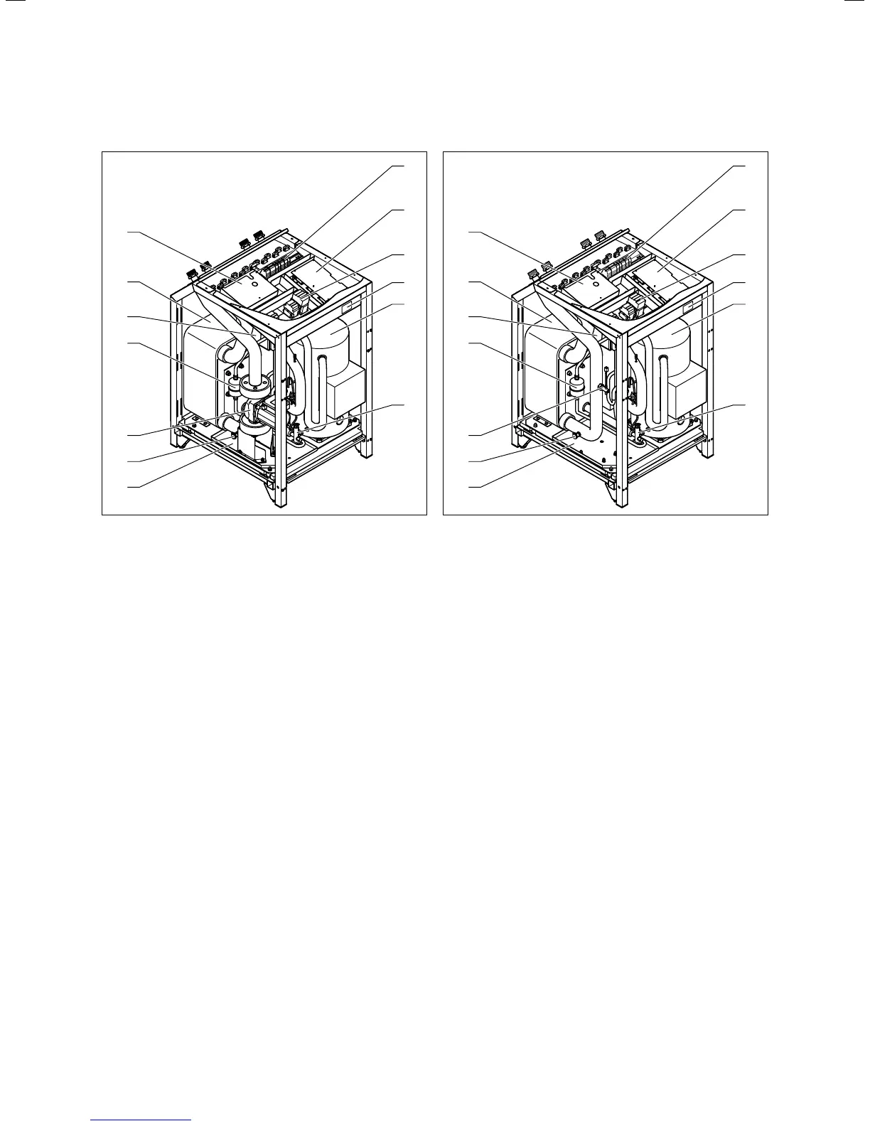
3.5 Front view when open (VWS)
Key
1 Electrical connections:
2 In-rush current limiter
3 Circuit breakers
4 Identification plate
5 Compressor
6 Expansion valve
7 Condensate pan
8 Brine circuit filling and emptying valve
9 Brine pump
10 Filter drying cartridge
11 Condenser
12 Evaporator
13 Controller PCB (under cover plate)
i
Some components, such as heating circuit pump,
3-way valves or electrical auxiliary heater, are
integrated into the VWS and VWW geoTHERM
heat pumps, but these must be placed on-site
and installed externally.
5
6
4
3
2
1
7
9
8
12
13
11
10
3.6 Front view when open (VWW)
Key
1 Electrical connections:
2 In-rush current limiter
3 Circuit breakers
4 Identification plate
5 Compressor
6 Expansion valve
7 Condensate pan
8 Brine circuit filling and emptying valve
9 Flow switch
10 Filter drying cartridge
11 Condenser
12 Evaporator
13 Controller PCB (under cover plate)

 Loading...


