Installation
Installation instructions geoTHERM 0020051574_04 19
4
Item. Number Description
1 1 Heat pump
12 2 Installation instructions, operating
instructions
2 2 Left and right side parts
Together in one box:
3 1 Operating panel, cover column
5 1 6-litre brine expansion tank, max. 300kPa
(3bar)
Together in one large bag:
4 1 Clamp for fastening the brine expansion
tank
11 1 Expansion relief valve for brine circuit,
1/2", 300kPa (3 bar)
6 1 VRC DCF radio clock signal receiver with
external sensor
7 4 VR 10 sensors
9 1 Control cable for vrnetDIALOG
10 1 Bag of small parts for fastening the brine
expansion tank
2 M6 flat-head screws for fitting the operat-
ing panel on the mounting plate
2 Tapping screws for the operating panel
mounting plate
4 Flat-head screws for fixing the side parts
to the frame
Together in one box:
8 4 Flexible connecting hoses (600 mm long,
heat source-side each with 1 1/2" inside
thread)
13 8 Bag with seals for connecting hoses for
the heating circuit (grey) and the brine/
well water circuit (yellow/green)
14 4 Lower and upper front cladding, front and
rear cover
4.3 Scope of delivery
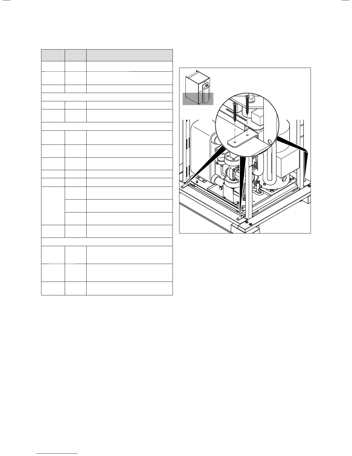
4.6 Removing the transport locks
4.5 Removing the transport locks
> Carefully remove the packaging and padding without
damaging the parts of the unit.
> Remove the transport locks with which the heat pump is
fixed to the pallet.
> Dispose of the transport locks correctly. These are no
longer required.

 Loading...


