Hydraulics installation
Installation instructions geoTHERM 0020051574_04 27
5
42a
42a
57
65
56
HK2-P
2
3
3
4
19 19
19
VF2
HK2
HKP
HKb-P
VFb
HKb
2
3
3
VF1
RF1
4
13b 13a 13a
2 BUS
2
BUS
2 BUS
13a
2 BUS
16
230 V~
3
230 V~
3
400 V~
5
3
3
4
2
2
3
13
42b
32
58
MM
4
HKa-P
VFa
HKa
2
3
3
M
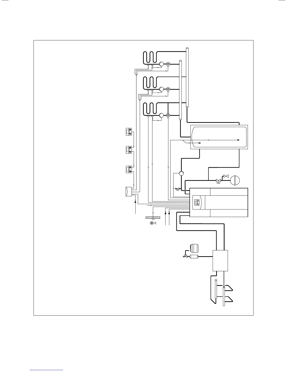
3 geoTHERM heat pump VWS ..0/2
4
allSTOR VPS/2 buffer cylinder
13a VR 90 remote control unit
13 Weather-controlled energy balance controller
13b VR 60 mixer module
16 VRC-DCF receiver with outside temperature sensor
19 Maximum thermostat
32 Capped stop valve
42a Expansion relief valve
42b Heating circuit diaphragm expansion tank
56 Heat pumps for brine filling unit
57 Brine expansion tank
58 Filling and drainage tap
65 Brine collecting tank
HKb-P
Heating circuit pump
HKa-P Heating circuit pump
HK2-P Heating circuit pump
HKP Heating circuit pump
VFb Flow temperature sensor
Key
HKb Heating circuit mixer
HKa Heating circuit mixer
HK2 Heating circuit mixer
RF1 Return temperature sensor
VFa Flow temperature sensor
VF2 Flow temperature sensor
VF1 Flow temperature sensor
5.3 Sample hydraulic scheme: Mixed circuit with buffer tank

 Loading...


