Hydraulics installation
Installation instructions geoTHERM 0020051574_04 33
5
42a
42a
40
57
65
56
HKa-P
2
2
3
3
4 4
19 19
VFa
HKa
SK2-P
VF2
SK2-P
(SK2-P)
67
66
HKP
HKb-P
VFb
HKb
2
3
3
43
42c
ZP
42a
SP
5
VF1
RF1
4
13b 13a 13a
2 BUS
2 BUS
2 BUS
LP/UV1
3
4
16
230 V~
3
230 V~
3
400 V~
5
400 V~
4
2
3
ZH
400 V~
5
3
3
3
3
3
2
2
3
13
42b
32
58
M
M
M
M
M
M
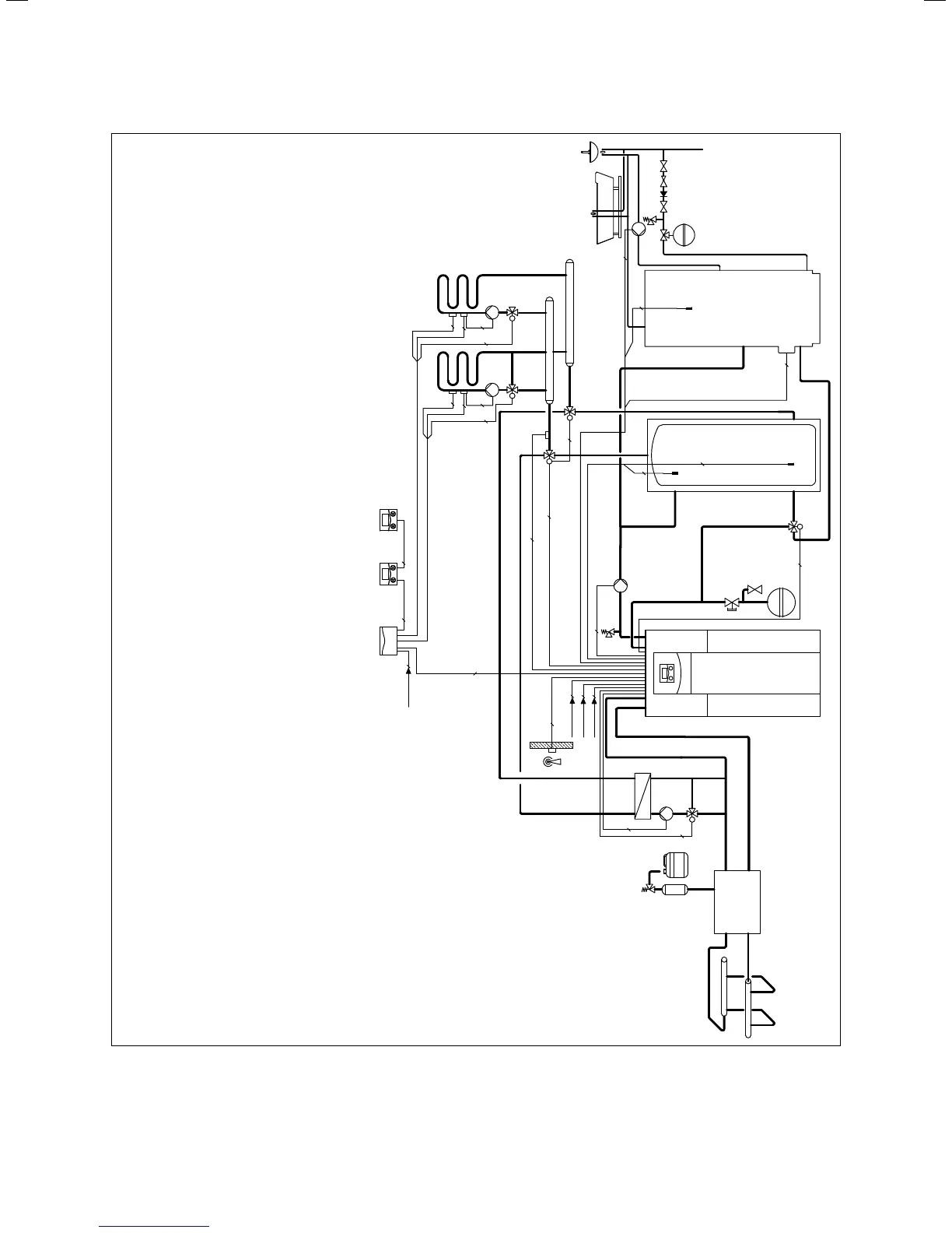
3 geoTHERM heat pump VWS ..0/2
4
allSTOR VPS/2 buffer cylinder
5 Domestic hot water cylinder
13a VR 90 remote control unit
13 Weather-controlled energy balance controller
13b VR 60 mixer module
16 VRC-DCF receiver with outside temperature sensor
19 Maximum thermostat
32 Capped stop valve
40 Heat exchanger, passive cooling
42a Expansion relief valve
42b Heating circuit diaphragm expansion tank
Hot water diaphragm expansion tank
43 Safety group, water connection
56 Heat pumps for brine filling unit
57 Brine expansion tank
58 Filling and drainage tap
65 Brine collecting tank
66 Pump, cooling circuit
67 Mixer, cooling circuit
HKa-P
Heating circuit pump
HKb-P Heating circuit pump
HKP Heating circuit pump
SP Cylinder temperature sensor
VFb Flow temperature sensor
ZP Circulation pump
Key
42c
HKa Heating circuit mixer
HKb Heating circuit mixer
LP/UV1 Heating/cylinder charging diverter valve
RF1 Return temperature sensor
SK2-P Diverter valve, cooling
VFa Flow temperature sensor
VF2 Flow temperature sensor
ZH Electric auxiliary heater
VF1 Flow temperature sensor
5.6 Sample hydraulic scheme: The mixed circuit with buffer
tank, DHW tank and external passive cooling

 Loading...


