Hydraulics installation
Installation instructions geoTHERM 0020051574_04 35
5
5.7 Connect the heat pump to the heating
circuit
b
Caution!
Risk of damage caused by condensation
water.
Condensation can cause corrosion.
> Insulate all of the pipes in the heating
circuit using vapour diffusion-tight insu-
lation.
b
Caution!
Risk of damage caused by overpressure
in the heating circuit.
During operation, overpressure may occur
in the heating circuit.
> Fit an expansion vessel and an expansion
relief valve in the heating circuit, as
required below.
For installing the heating installation, EN 12828 requires the
following:
– a filling valve, in order to fill the heating installation with
water or to be able to drain water (installed in the unit at
the factory).
– a diaphragm expansion tank in the return of the heating
circuit,
– a safety overpressure valve (at least DN 20, opening
pressure 3 bar) with a pressure gauge (safety group) in
the supply of the heating circuit, immediately behind the
heat pump,
– an air/dust separator in the return of the heating circuit.
a
Danger!
Risk of scalding from steam or hot water.
If there is overpressure, steam and/or hot
water is blown out via the blow-off line of
the safety overpressure valve.
> Install a blow-off line the same size as
the outlet opening in such a way that
there is no risk to people caused by
steam and/or hot water when it is blown
out.
> Install the blow-off line in a frost-free environment
so that it always remains easily accessible and visible.
We recommend that you install a Vaillant safety group and
a drain pipe.
> Fit the heating flow and return and all the components.
> Dimension and fit an external heating circuit pump
(to be fitted on-site).
> If required, fit a heating/cylinder charging diverter valve
(to be fitted on-site).
> Connect the flow pipe (1) (¬Fig.5.8).
> Connect the return pipe (2) (¬Fig.5.8).
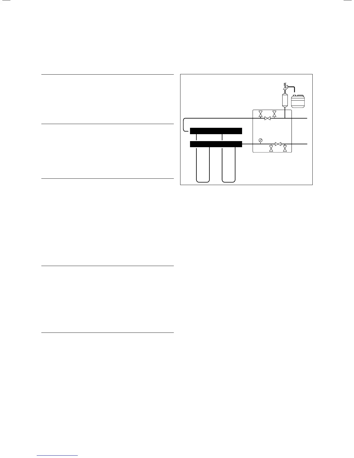
5.8 Connecting the heat pump to the brine
circuit (VWS only)
64
48
56
70 72
62
57
42a
63
61
65
5.9 Fittings in the brine circuit
Key
42a Expansion relief valve
48 Pressure gauge
56 Heat pumps for brine filling unit
57 Brine expansion tank
61 Stop valve
62 Stop valve
63 Stop valve
64 Stop valve
65 Brine collecting tank
70 Stop valve
72 Stop valve
Vaillant recommends that you install the Vaillant heat pump
brine filling unit. By doing this, it is then possible to carry
out a preparatory partial bleed of the brine circuit, e. g. the
flow and return lines of the brine circuit to the unit.
> When installing this, observe the ¬ installation instruc-
tions for the heat pump brine filling unit.

 Loading...


