Electrical installation
Installation instructions geoTHERM 0020051574_04 45
7
7.2 Electronic switchbox
PE
L1 L2 L3
T1 T2 T3
A1 A2
L1 L2 L3
T1 T2 T3
A1 A2
L1 L2 L3
T1 T2 T3
A1 A2
A1
L1 L2 L3
T1 T2 T3
A2
A1
L1 L2 L3
T1 T2 T3
A2
A1
L1 L2 L3
T1 T2 T3
A2
PE
L1 L2 L3
T1 T2 T3
A1 A2
L1 L2 L3
T1 T2 T3
A1 A2
L1 L2 L3
T1 T2 T3
A1 A2
A1
L1 L2 L3
T1 T2 T3
A2
A1
L1 L2 L3
T1 T2 T3
A2
1
2
3
4
15
14
13
12
11
10
9
5678
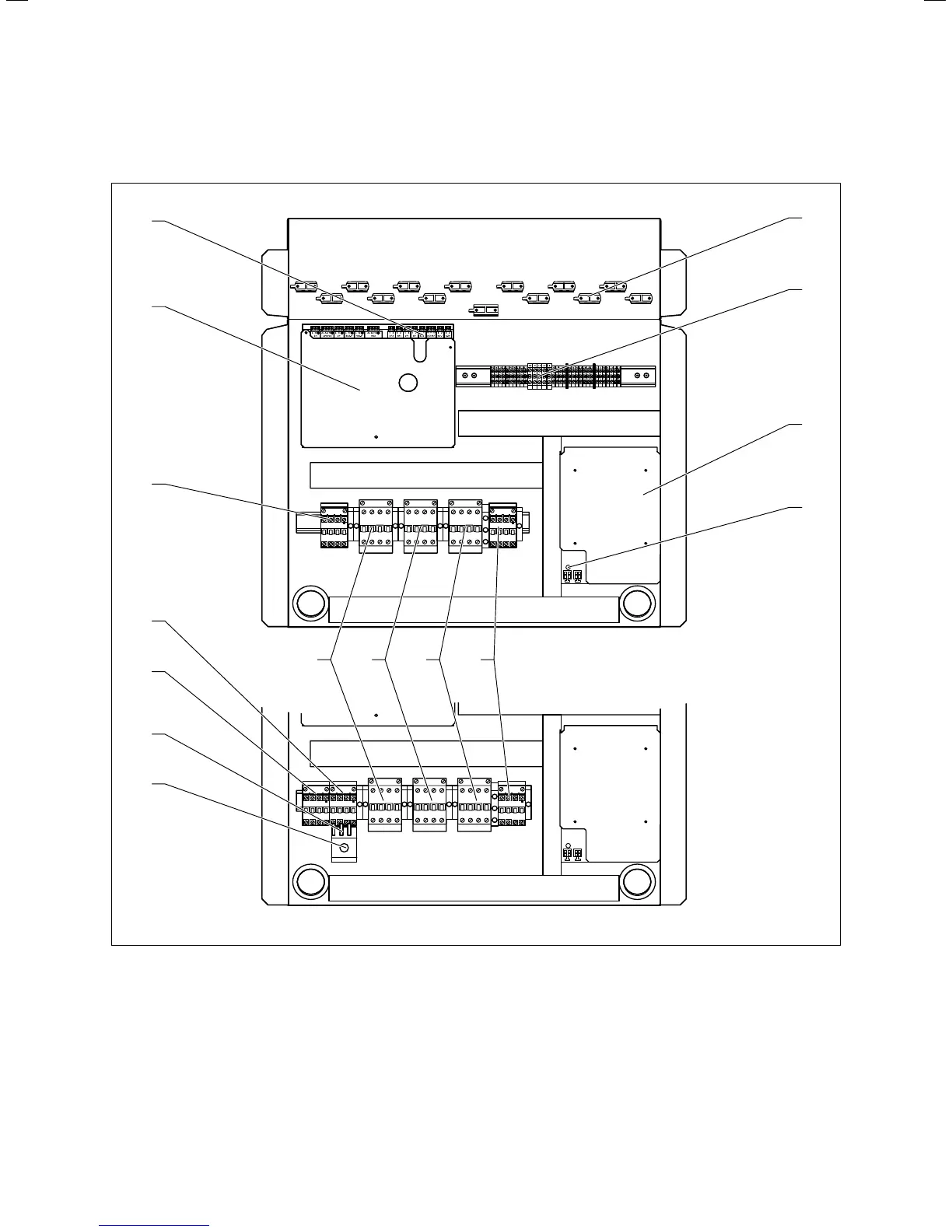
7.1 Electronic switchbox VWS and VWW 220/2 - 300/2
Key
1 Strain relief clamps
2 Electricity supply connection terminals
3 In-rush current limiter
4 Green LED for voltage supply
5 Protection for external electrical auxiliary heater
6 Compressor protector contactor
7 Compressor control contactor
8 In-rush current limiter contactor
9 VWW only: Control button for well pump overcurrent
10 VWW only: thermal overcurrent relay
11 VWW only: Well pump control contactor
12 VWW only: Well pump protector contactor
with overcurrent relay (motor protection)
13 (VWS only) Protector contactor, brine pump
14 Controller PCB
15 Connection strip for sensors and external components

 Loading...


