Electrical installation
Installation instructions geoTHERM 0020051574_04 49
7
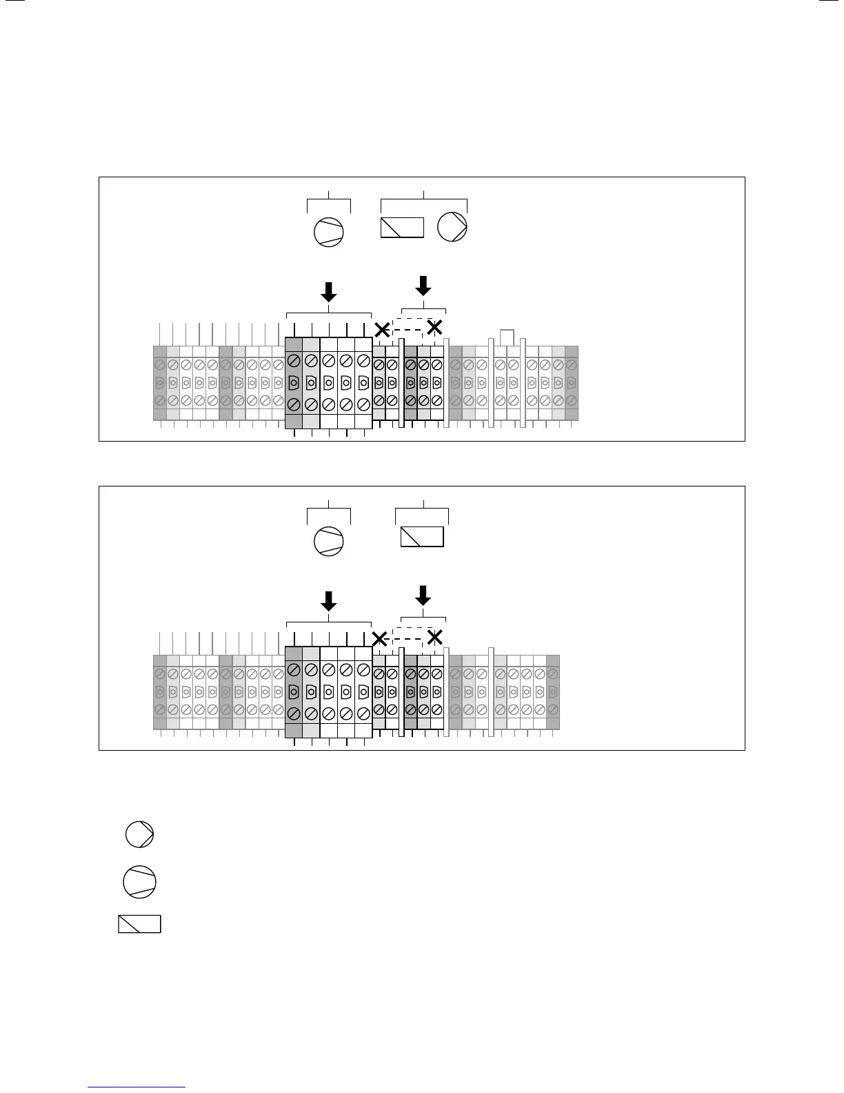
7.3.2 Duel-circuit supply heat pump rate
(electric wiring diagram 2)
L3 L2 L1NPEL3 L2 L1NPE 1 2 N PELNPELNPEL3N
PE L2 L1L3N
SS
400 V
50 Hz
1
+
2
230 V
50 Hz
3
7.5 Duel-circuit supply VWS heat pump rate
L3 L2 L1NPEL3 L2 L1NPE L3 L2 L1N PELNPELNPEL3N
PE L2 L1L3N
400 V
50 Hz
1 2
230 V
50 Hz
3
7.6 Duel-circuit supply VWW heat pump rate
Key
Pump (brine circuit pump)
Compressor
Controller
In this case, the heat pump is operated using two electricity
rates (two consumption meters). A permanent standard rate
electricity supply (2) ensures the operation of the auxiliary
consumers (circulation pumps, controllers, etc.) across a
separate electricity meter. The additional reduced rate
electricity (1) for the compressor is supplied via a second
electricity meter and can be suspended by the power com-
pany at peak times.
The duration and frequency of the lock-out is determined
by the power company or must be clarified with them.
> Remove the bypass pipework (dashed lines, 3).
> Connect the permanent electricity supply to the stand-
ard rate mains supply (2).

 Loading...


