Electrical installation
50 Installation instructions geoTHERM 0020051574_04
7
> Connect the standard rate electricity supply to the
reduced rate mains supply (1).
> Connect the contact of the control system signal receiver
to terminal 13 “EVU” (energy supplier) (¬Fig. 7.1 8).
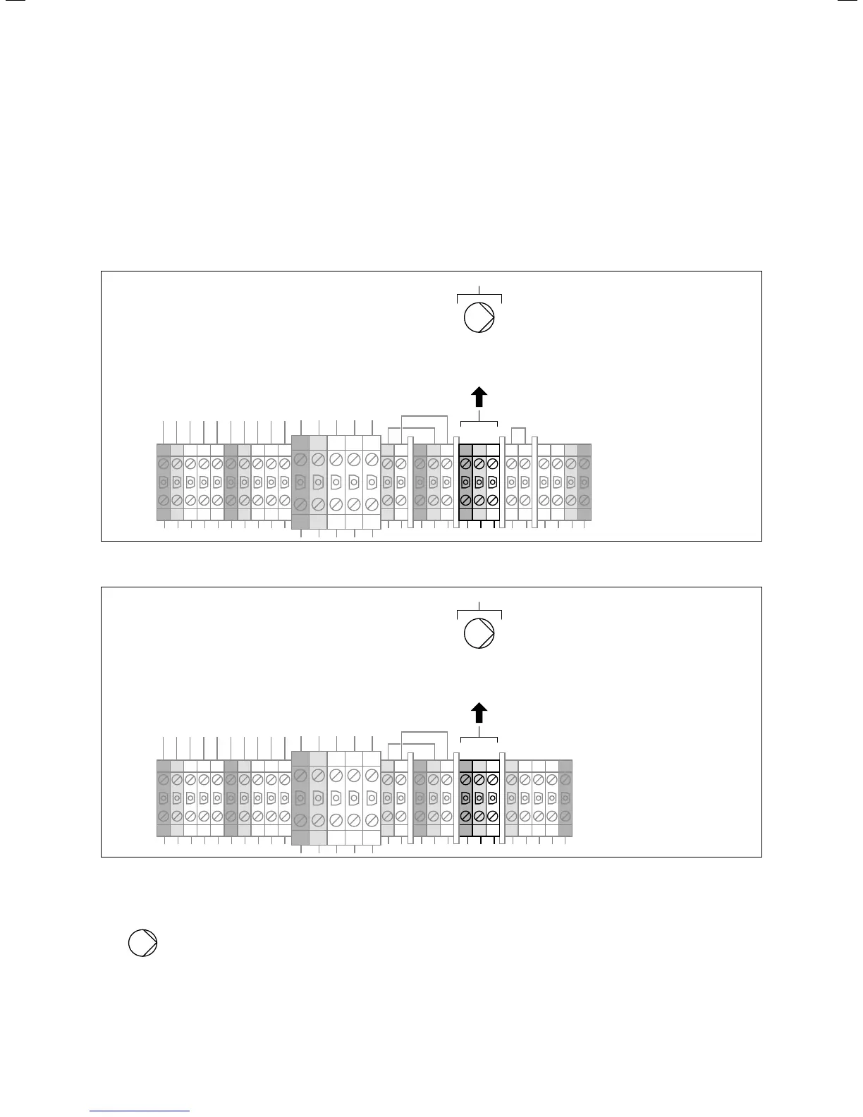
7.3.3 Connecting the external heating circuit
pump
L3 L2 L1NPEL3 L2 L1NPE 1 2 N PE
SS
LNPEL3N
PE L2 L1L3N
LNPE
U
max
= 230V
I
max
= 2 A
1
7.7 Connecting the external heating circuit pump VWS
L3 L2 L1NPEL3 L2 L1NPE L3 L2 L1N PELNPELNPEL3N
PE L2 L1L3N
U
max
= 230V
I
max
= 2 A
1
7.8 Connecting the external heating circuit pump VWW
Key
Pump (heating circuit pump)
> Connect the external, heating circuit pump (to be fitted
on-site) with I
max
= 2 A and U
max
= 230 V 1. If these values
are exceeded, install a relay/circuit breaker that is to be
fitted on-site and switch the pump using this.

 Loading...


