Electrical installation
58 Installation instructions geoTHERM 0020051574_04
7
b
Caution!
Risk of damage from overload!
The maximum power for all actuators/con-
sumers that are connected to the controller
PCB must not exceed 4 A.
> Observe the following connection limits:
I
max
= 2 A, U
max
= 230 V
The controller PCB has a cover plate for protection and this
cover plate has openings for the eBUS/vrDIALOG 810/2
connection (15) and for the voltage supply LED (18).
To replace the fuses (17) or (19), you must remove the
cover plate.
7.5 Installing the supplied accessory
The following must be connected for the sample
hydraulic scheme for hydraulic scheme 1 (¬Fig.5.2):
– VRC-DCF receiver with outside temperature sensor
– VF2 flow temperature sensor
The following must be connected for the sample
hydraulic scheme for hydraulic scheme 2 (¬Fig.5.3):
– VRC-DCF receiver with outside temperature sensor
– VF2 flow temperature sensor
– VF1 flow temperature sensor buffer tank
– RF1 Return temperature sensor buffer tank
The following must be connected for the sample
hydraulic scheme for hydraulic scheme 3 (¬Fig.5.4):
– VRC-DCF receiver with outside temperature sensor
– VF2 flow temperature sensor
– DHW tank sensor SP
The following must be connected for the sample
hydraulic scheme for hydraulic scheme 4 (¬Fig.5.5):
– VRC-DCF receiver with outside temperature sensor
– VF2 flow temperature sensor
– DHW tank sensor SP
– VF1 flow temperature sensor buffer tank
– RF1 Return temperature sensor buffer tank
The following must be connected for the sample
hydraulic scheme for hydraulic scheme 10 (¬Fig.5.6):
– VRC-DCF receiver with outside temperature sensor
– VF2 flow temperature sensor
– DHW tank sensor SP
– VF1 flow temperature sensor buffer tank
– RF1 Return temperature sensor buffer tank
7.5.1 Installing the VR 10
The VR 10 standard sensor is designed in such a way that it
can be fitted in three different positions, depending on your
requirements:
– as an immersion sensor, e. g. as a tank sensor
to a tank sensor pocket.
– as a flow sensor in a hydraulic switch.
– as a clamp-on sensor on the heating pipe
in the supply or return.
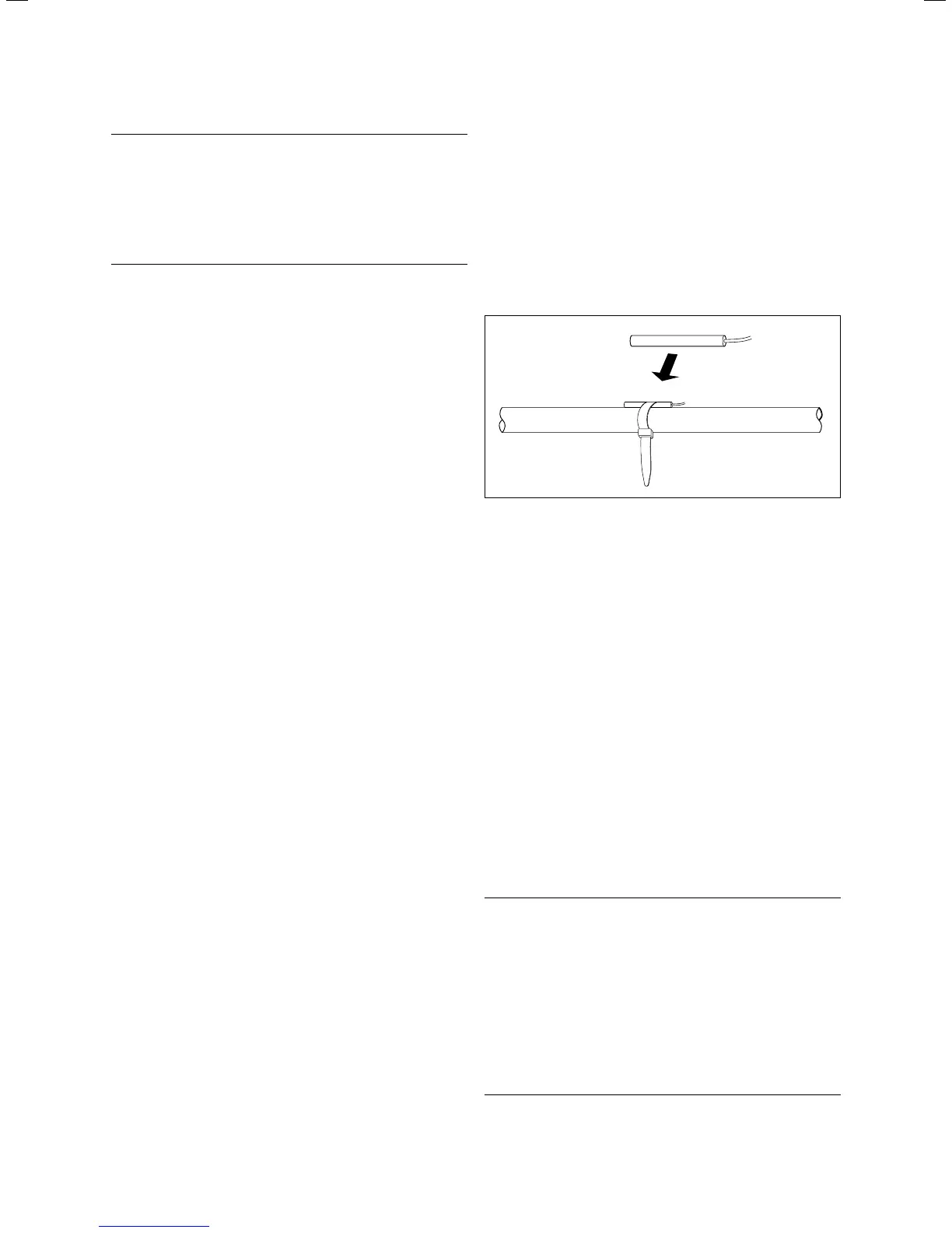
7.19 Installing the VR 10 standard sensor as a clamp-on sensor
You can use the enclosed strap to secure the sensor as a
clamp-on sensor to the heating pipe in the supply or return.
We recommend that the pipe together with the sensor be
insulated
to ensure optimum temperature measurement.
> Install the VR 10 standard sensor(s) in accordance with
the requirements of the hydraulic scheme and connect it
to the respective terminals on the controller PCB (¬Fig.
7.1 8).
The controller automatically recognises the supplied sensor.
VR 10 sensors do not have to be registered or configured.
7.5.2 Installing the VRC DCF
The supplied VRC DC receiver must always be installed,
even if another DCF receiver is already installed. This can-
not be used for the heat pump. This also applies for sys-
tems that have a fixed value configuration and systems that
have the VRC 620/630 bus modular control system.
b
Caution!
Risk of malfunction!
If the supplied VRC DCF receiver with exter-
nal sensor has not been installed, the oper-
ating panel display shows a temperature of
-60 °C. It is not possible to correctly control
the flow temperature and the external elec-
tric auxiliary heating. No warning message
is recorded in the Error History.
> Install the supplied VRC DCF receiver
with external sensor.

 Loading...


