Adapting the appliance to the heating system
Installation instructions geoTHERM 0020051574_04 77
9
Display shown Description Factory setting
15
22
20
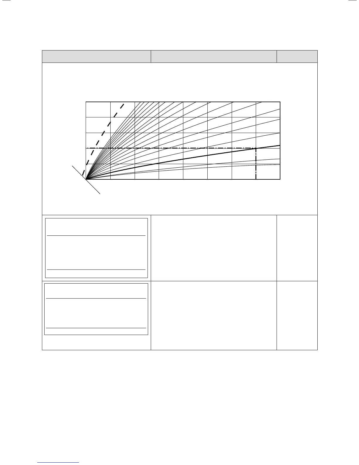
Target room
temperature
Outside temperature in °C
4.0 3.5
3.0
2.5
2.0 1.8
1.5
1.0
0.6
0.8
0.2
0.1
0.4
70
60
50
40
30
15 10 5 0 -5 -10 -15 -20
1.2
Flow temperature
in °C
Heating curves
HK2 C2
Parameters
Type Fixed value
Max. limit outs.temp. >20 °C
Comp. starts at -120 °C
>Select temperature
T
his display appears when “Fixed value” has been
set.
For energy balancing, the display “Comp. starts at”
also appears.
Buffer tank
C3
Information
Flow Temp. Setpoint 41 °C
T buffer top <VF1> 29 °C
T buffer Bottom <RF1> 25°C
This menu is only displayed if a buffer tank is used
(e.g. Hydraulics diagram 2, 4 or 10).
Flow Temp. Setpoint: Target flow temperature
T buffer top <VF1>: Temperature of the buffer tank
flow temperature sensor VF1
T buffer Bottom <RF1>: Temperature of the buffer
tank return temperature sensor RF1
9.6. Menu C: Set parameters for the heating system

 Loading...


