Adapting the appliance to the heating system
78 Installation instructions geoTHERM 0020051574_04
9
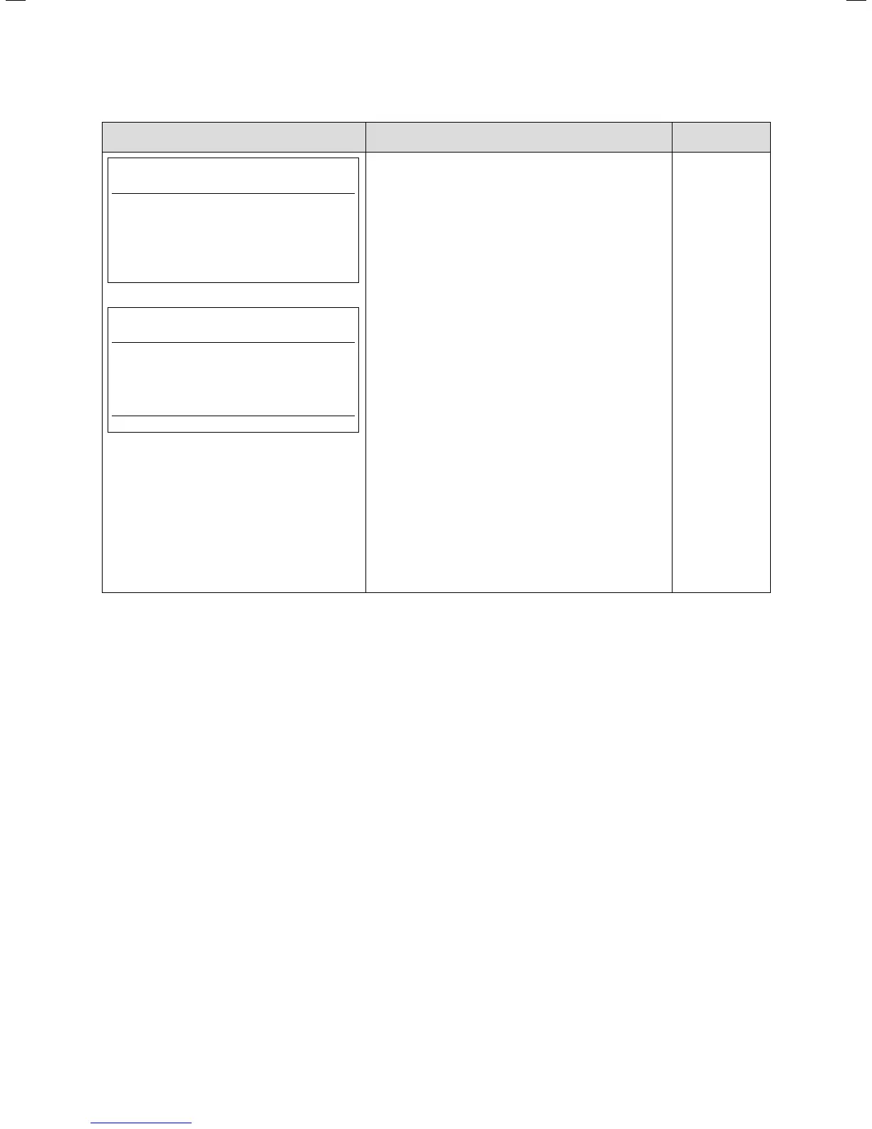
Display shown Description Factory setting
HK2
C4
Information
Flow Temp. Setpoint 41 °C
Flow Temp. VF2 30 °C
Status of pump OFF
°mins lag/gain -183°min
HK2
C4
Parameters
Flow Temp. Setpoint 41 °C
Flow Temp. VF2 29 °C
Status of pump OFF
Status hydr. mixer Open
For direct heating mode (e.g. Hydraulics diagram 1 or
3), the upper menu is displayed.
The lower menu is only displayed if a buffer tank is
used (e.g. Hydraulics diagram 2, 4 or 10 and when
VR 60 is used, including repeatedly).
Flow Temp. Setpoint: Flow temperature for the heat-
ing circuit
Flow Temp. VF2: Current flow temperature VF2.
°mins lag/gain: The °mins lag/gain is the sum of the
difference between TARGET flow temperature
and ACTUAL flow temperature per minute. The
heat pump starts at a particular heat deficiency
(see energy balance control (¬Ch.9.4.2)).
Status of pump: Indicates whether the pump is
turned on or off (ON/OFF).
Status hydr. mixer: The OPEN/CLOSED indication
describes the direction in which the control sys-
tem is driving the mixer. If the mixer is not acti-
vated, OFF appears.
If a VR 60 is connected, the lower menu appears sev-
eral times (for each heating circuit).
9.6. Menu C: Set parameters for the heating system

 Loading...


