Appendix
32 Installation instructions 0020237057_01
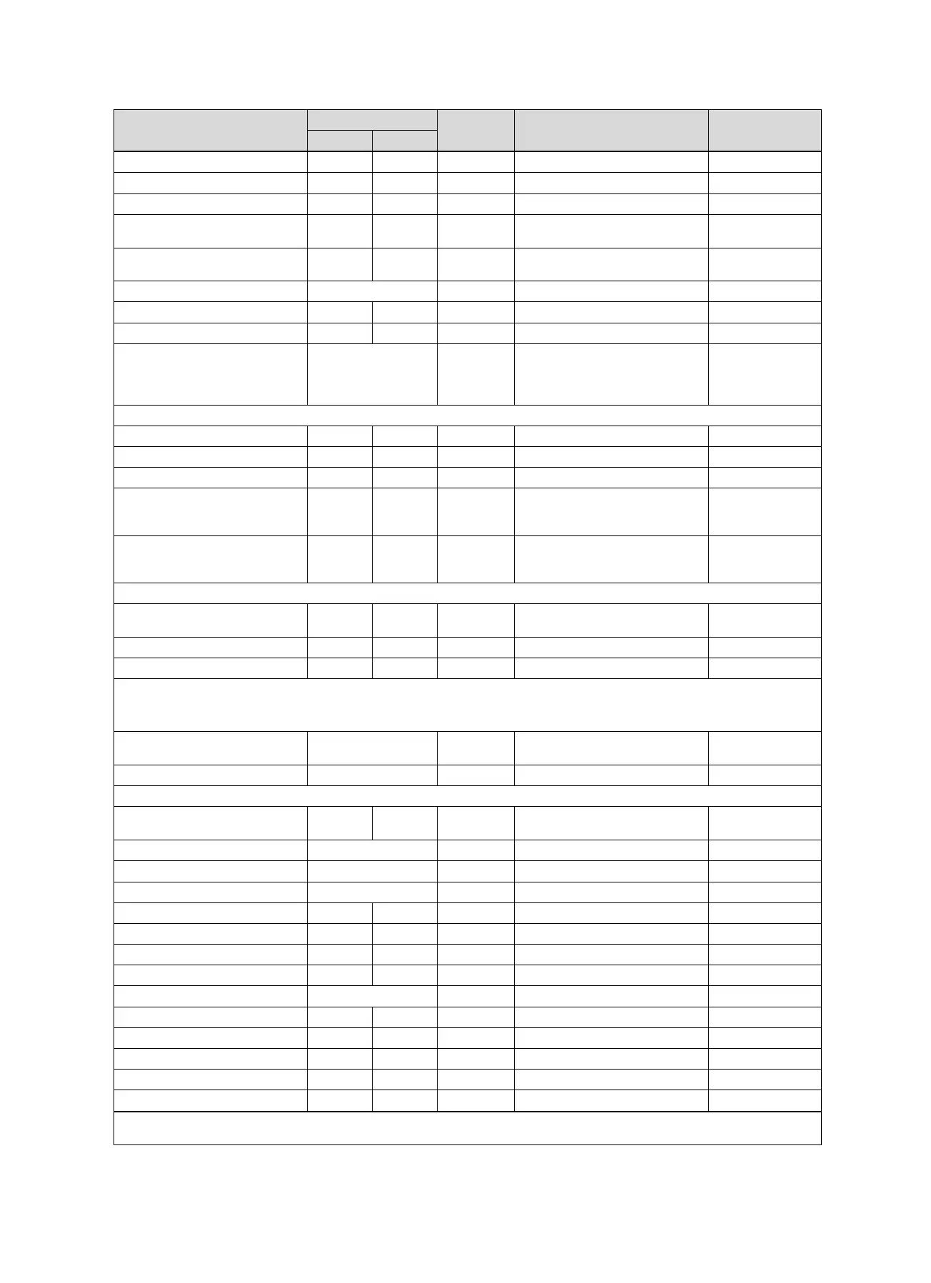
Setting level Values Unit Increment, select Default setting
Min. Max.
Alternative point off, -20 40 ℃ 1 off
T. emergency mode 20 80 ℃ 1 25
Auxiliary heater type condens., non cond., Electric condens.
Energy supplier HP off, BH off, HP&BH off, Heat.
off, Cooling off, Ht./cl. off
HP off
Auxiliary heater for Inactive, Heating, DHW,
DHW+heat.
DHW+heat.
System flow temp. Current value ℃
Buff. cyl. offs. 0 15 K 1 10
Actuation reversal Off, On Off
Actuation sequence Current sequence of
the heat generators
without auxiliary heat-
ing
System diagram configuration ----
System diagram 1 16 1, 2, 6, 7, 8, 9, 10, 11, 12, 13, 16 1
Config.: VR71 1 11 1 3
Config.: VR70 addr. 1 1 12 1 1
MA VR70, addr. 1 No funct., Charg.pump, Circ.
pump, Cool.signal, Leg. pump,
HC pump
No funct.
MA VR71 No funct., Charg.pump, Circ.
pump, Cool.signal, Leg. pump,
TD con.
No funct.
Additional module ----
Multi-funct. output 2 HK-2P, Circ. pump, Dehumid.,
Zone, Leg. pump
Circ. pump
Aux. heater output off, Stage 1, Stage 2, Stage 3 Stage 3
Multi-funct. Input Not conn., Circ. boost, PV Circ. boost
Heat pump 1 ----
Heat generator 1 ----
Additional module ----
Status Current value Standby, Heat. mode, Cooling,
DHW
Current flow temp. Current value ℃
HEATING1 ----
Type of circuit Inactive, Heating, Fixed val.,
DHW, Ret.fl.incr.Pool,
Heating
Status Current value off, Heat. mode, Cooling, DHW
Target flow temp. Current value ℃
Target flow temp. pool Current value ℃
Target flow temp.: Day 5 90 ℃ 1 65
T.fl.temp.: Set-back 5 90 ℃ 1 65
Target return temp. 15 80 ℃ 1 30
Min. cool. fl. tgt temp. 7 24 ℃ 1 20
Current temperature Current value ℃
Excessive temp. 0 30 K 1 0
Max limit outs.temp. 10 99 ℃ 1 21
Minimum temperature 15 90 ℃ 1 15
Maximum temperature 15 90 ℃ 1 90
Auto Off mode Eco, Set-back Eco
* If no fault is present, the status is No fault. If there is a fault, Fault list appears and you can read the fault message in the "Fault mes-
sages" section.
 Loading...