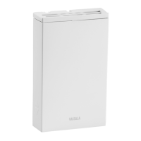
Transmitter Parts
Figure 1 GMW80 Series Transmitter Parts
1 = Opening tab.
2 = Screw terminals. The wiring information is marked on the mounting base
next to the terminals.
3 = Barrier to prevent the cable from being routed below the GM10
measurement module. The area to avoid is marked No cable on the
mounting base.
4 = Orientation arrow. Should point up after mounting base has been installed.
5 = Opening for cable when wiring from behind(recommended).
6 = Place for zip tie (optional, for cable strain relief).
7 = Breakaway tab for routing the cable from below.
8 = Locking screw. Supplied with the transmitter.
9 = Breakaway tab for routing the cable from above.
10 = CO
2
level indicator LEDs (on models with letter A). See CO2 Level Indicator
LEDs on page11.
11 = Display (on models with letter D). See Display on page9.
12 = Setpoint wheel (on models with letter T). See Temperature Setpoint
Potentiometer on page12.
7
2 Product Overview
 Loading...