The relay mode of GMP251 and GMP252 probes has been designed to use 12 mA as the
relay control current. Use only 12 mA for the set_value configuration when using the
relay box with GMP251 and GMP252.
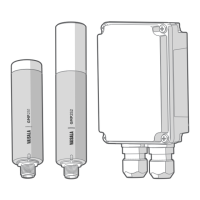
1.4 Probe and Relay Box Wiring
Function Wire Color
Output control
Voltage output
Current output
GND
Power in
Gray
White
Black
Blue
Brown
GMP25X Probe
Voltage
NC
NC
Current
GND
Power
Power
GND
Vout
GND
Relay
Relay
Inputs / Outputs
Relay Box Input/Output
GND
Power supply to GMP25x
Voltage output from GMP25x *
GND
Relay contact
Relay contact
Power supply to GMP25x:
20 ... 30 VDC (for current output)
*) Voltage output from GMP25x is internally connected to Vout
Figure 1 Probe and Relay Box Wiring
1. Open the relay box screws and remove the cover.
2. Lead the GMP251/252 probe connection cable with open wires (223263SP/244669SP/
216546SP) through the left cable gland and connect the open wires to the screw
terminals as shown in Figure 1 (page 10).
3. Lead the relay box input/output cable through the right cable gland and connect the
wiring as shown in Figure 1 (page 10).
Do not switch on the power supply before you have completed the
wiring and reattached the relay box cover.
CAUTION!
4. After the wiring is complete, reattach the relay box cover and switch on the 20 ... 30
VDC power supply.
Relay Box for GMP250 Carbon Dioxide Probes Quick Guide M211920EN-C
10
 Loading...