1 Radiation shield. Do not remove for installation, only when replacing the sensor or filter.
2 Long screws that keep the radiation shield in place (2 pcs), 3 mm hex socket.
3 Sensors for humidity and temperature under PTFE membrane filter (ASM210856SP).
4 Component board.
5 Transmitter body.
6 Screws for pole mounting (2 pcs, medium size Pozidriv).
7 Clamp for pole mounting. The holes are threaded for the included pole mounting screws
and set screw.
8 Set screw (medium size Pozidriv). Install after pole mounting to stop the transmitter from
turning.
9 Medium size crosshead screws (6 pcs).
10 Transmitter cover.
11 Cable gland. Suitable for 4 ... 8 mm diameter cable.
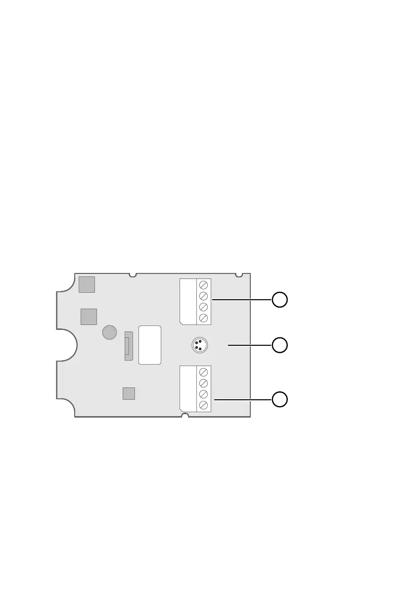
2.6 Component Board
All HMDW110 transmitter models use the same component board, which has 2 output types:
Modbus mode (RS-485) and analog mode (current output). The output type is selected when
ordering the device. See the type label of the device to see the chosen output type.
The component board has also a service port for configuration and calibration use.
8 T-
7 T+
6 HUM-
5 HUM+
4 Pwr+
3 Pwr-
2 RS485-
1 RS485+
Service
Port
1
2
3
Figure 4 HMDW110 Series Component Board
1
Terminal block for 4 ... 20 mA current loop outputs. Must be disconnected when the
transmitter is powered through RS-485 connection in the lower terminal block (terminals
1 ... 4).
2 Service port connector (4-pin M8)
3 Terminal block for RS-485 output. For Modbus or RDP100 remote display panel
connection.
Chapter 2 – Product Overview
13

 Loading...


