1.6 Indigo Transmitter Base
1 4
5
6
3
INDIGO 202
DIGITAL TRANSMITTER
Serial No. SX12345678
24V
IN
RS485
A. Relay
B. Relay
2
c
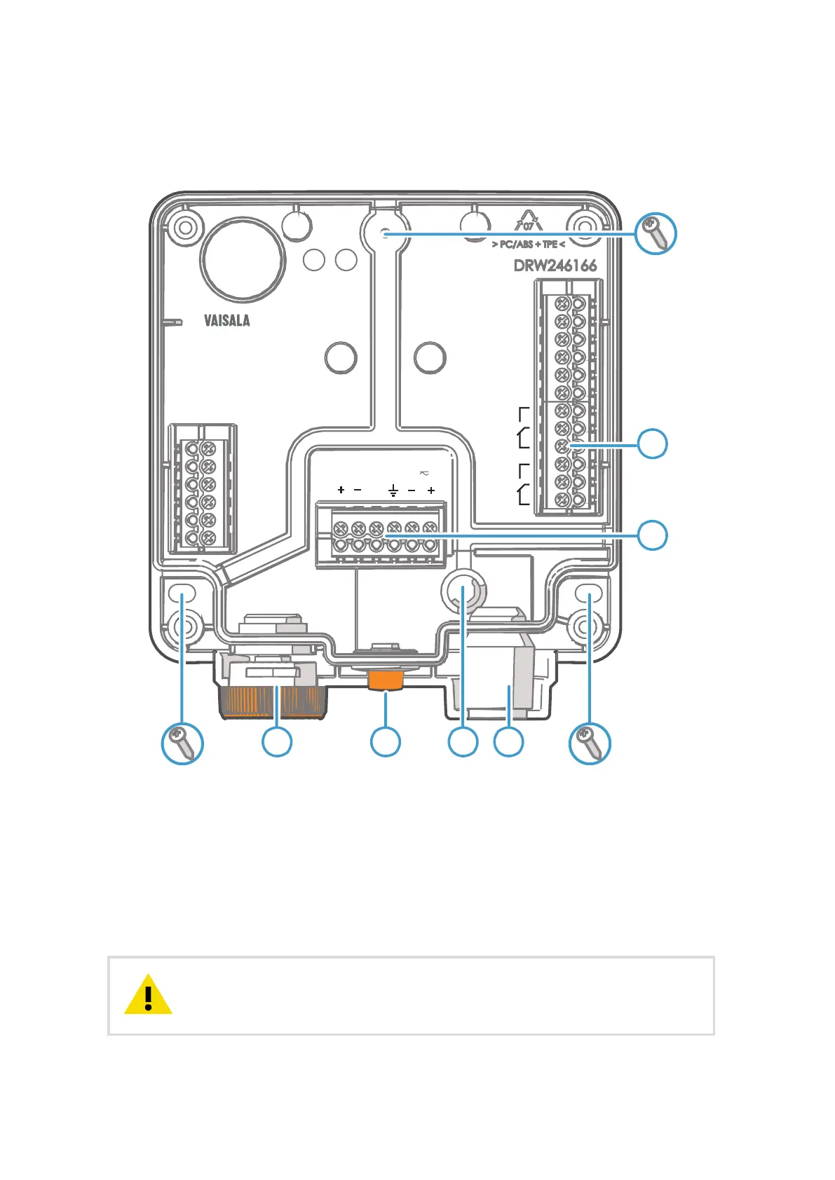
Figure 4 Indigo 202 Transmitter Base Main Parts and Screw Positions
1 Probe and probe cable connector inside the locking wheel
2 Wireless (WLAN) configuration interface activation button
3 Wiring from the back: cut open the seal
4 Rubber cable lead-through with strain relief
5 Screw terminals for relays A and B
6 Screw terminals for 24 V power supply input and RS-485 (Modbus) connection
Do not energize the power supply before the wiring has been connected.CAUTION!
M211967EN-E
10

 Loading...