List of Figures
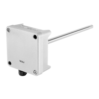
Figure 1 Probe Connection Options and Wireless Interface
Ex
amples (GMP251 Example)...........................................................................7
Figure 2 Serial Number on Probe Body (GMP251 Example)....................................8
Figure 3 Indigo Transmitter Parts....................................................................................9
Figure 4 Indigo Display with One Parameter ............................................................ 10
Figure 5 Indigo Display with Relays, Three Parameters and WLAN
Notification..........................................................................................................10
Figure 6 Indigo Display in Graph Mode.........................................................................11
Figure 7 Desktop and Mobile Example Views............................................................ 12
Figure 8 Indigo 202 Transmitter Base Main Parts and Screw Positions..............14
Figure 9 Indigo Wiring Options...................................................................................... 15
Figure 10 Attaching Probes and Cables to Indigo.......................................................16
Figure 11 WLAN and RS-485 DIP Switches on Indigo 202 Circuit Board............ 18
Figure 12 Wireless Configuration Interface, Desktop Browser View......................21
Figure 13 Enabling and Accessing Indigo's Wireless Configuration Interface... 22
Figure 14 Indigo Login View.............................................................................................24
Figure 15 User Level (User/Admin) in Upper Right Corner of Menu View...........25
Figure 16 Measurements View (Desktop Browser)....................................................27
Figure 17 Status View (CO
2
Probe Example, Desktop Browser)............................ 28
Figure 18 Calibration Menu (CO
2
Probe Example, Desktop Browser)..................30
Figure 19 Relay Configuration Options (CO
2
Probe Example)................................41
Figure 20 Relay Icons on the Optional Display (Relay A Active, Relay
B Not Active)......................................................................................................42
Figure 21 Calibration Menu Main View.......................................................................... 45
Figure 22 Start Calibration Button..................................................................................46
Figure 23 Measurement Selections, CO
2
Probe Example.........................................48
Figure 24 Compensation Setpoint and Power-Up Default Selection,
CO
2
Probe Example......................................................................................... 49
Figure 25 Measurements Tab, CO
2
Probe Example....................................................50
Figure 26 Diagnostics Tab, CO
2
Probe Example...........................................................51
Figure 27 Configuration Tab, CO
2
Probe Example......................................................52
Figure 28 Additional Steps Needed to Connect Notification..................................56
Figure 29 Indigo Transmitter Dimensions in Millimeters (mm).............................. 64
List of Figures
3

 Loading...