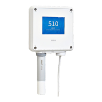
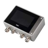
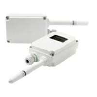
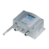
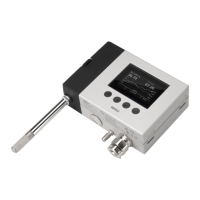
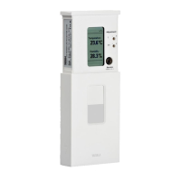
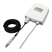
2.3 Indigo 520 transmitter parts
1 Touchscreen display
2 Transmitter base
3 Transmitter cover
4 Cable gland for Ethernet cable and optional analog output cable (M20×1.5 lead-through)
5 Cable glands for probe connection cables (M16×1.5 lead-throughs)
6 Cable gland for optional relay cable and power cable in the PELV and AC (mains) power
supply options (M20×1.5 lead-through)
7 Hex screws for opening the cover
2.3.1 Cable gland and conduit options
The transmitter has 4 lead-throughs. The glands or conduit fittings for the lead-throughs are
selected when ordering the transmitter. Unused lead-throughs are plugged.
The following figure shows examples of dierent cable gland and conduit configurations
available from Vaisala.
Indigo 520 User Guide M212287EN-A
10

 Loading...
