List of figures
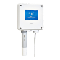
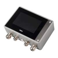
Figure 1 Indigo 520 cable gland and conduit options, example
configurations.................................................................................................... 11
Figure 2 Standard wall mounting.................................................................................18
Figure 3 Transmitter mounting dimensions.............................................................. 18
Figure 4 Wall mounting with adapter plate.............................................................. 19
Figure 5 Adapter plate dimensions............................................................................ 20
Figure 6 Attaching DIN rail clip fasteners.................................................................. 21
Figure 7 Attaching mounting plate to fixing brackets - vertical
pole mounting..................................................................................................22
Figure 8 Attaching transmitter to mounting plate - vertical pole
mounting........................................................................................................... 22
Figure 9 Example of stripped AC (mains) power cable........................................ 25
Figure 10 M20×1.5 cable gland with split bushing....................................................28
Figure 11 Attaching probes to transmitter using probe cable connector.........30
Figure 12 Measurements (Home) view on touchscreen.......................................... 31
Figure 13 Configuration menu on touchscreen......................................................... 32
Figure 14 Web interface and main views.................................................................... 33
Figure 15 Network settings on touchscreen.............................................................. 36
Figure 16 Date and time settings on touchscreen.................................................... 37
Figure 17 Web interface, Measurements (Home) view........................................... 39
Figure 18 User creation page.........................................................................................40
Figure 19 Network settings in web interface............................................................. 44
Figure 20 Date and time settings in web interface...................................................45
Figure 21 Configurable Home views on touchscreen..............................................48
Figure 22 Analog outputs configuration menu on touchscreen,
General tab active...........................................................................................50
Figure 23 Relays configuration menu on touchscreen, Relay 2 tab active........ 53
Figure 24 Behavior of relay that activates above limit, with hysteresis..............55
Figure 25 Analog outputs configuration menu in web interface.......................... 57
Figure 26 Relays configuration menu in web interface........................................... 59
Indigo 520 User Guide M212287EN-A
4

 Loading...
