Analog outputs are not available in transmitters that are powered with Power over Ethernet
(PoE).
Use the touchscreen or web interface to change the output mode (for example, 0 … 5 V or
4 … 20 mA) and scaling of the analog outputs.
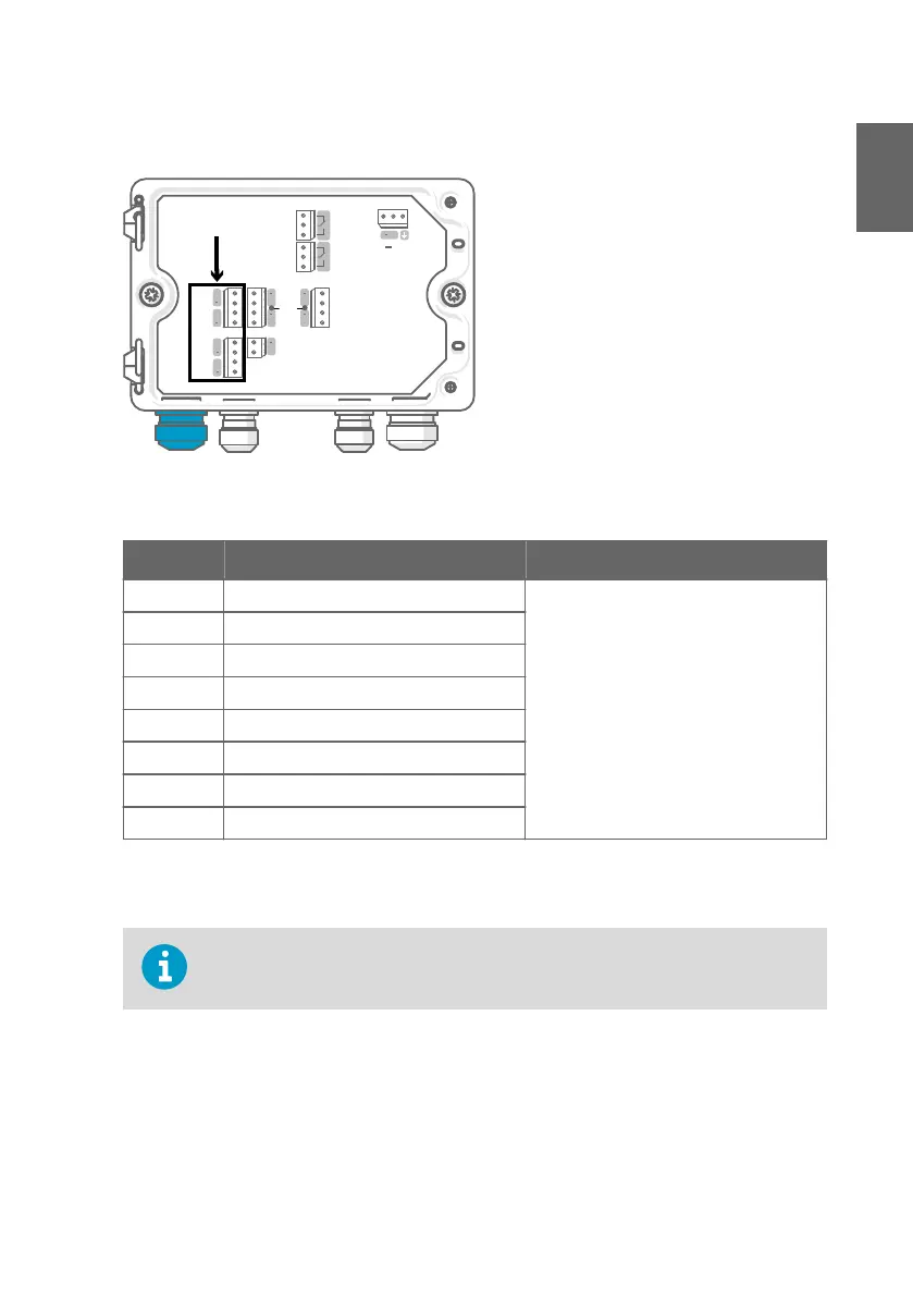
ANALOG OUTPUTS
RELAY 1RELAY 2
+
+
+
+
+
+
+
+
+
CH1
CH2
CH3
CH4
RS-485
PROBE
24 VOUT
ANALOG
INPUT
NO COM NC NO COM NC
1
2
For the M20×1.5 cable gland ordered
together with the transmitter from Vaisala,
the cable diameter is 5.0 … 8.0 mm
(0.20 … 0.31 in). Tightening torque for the
cable gland is 8 Nm.
For the M20×1.5 cable gland with split
bushing, the cable diameter is 7 mm
(0.28 in).
Table 8 Analog output terminals
Terminal Function Notes
CH1 + Analog output channel 1 +
Max. wire size: 2.5 mm
2
(14 AWG)
CH1 - Analog output channel 1 -
CH2 + Analog output channel 2 +
CH2 - Analog output channel 2 -
CH3 + Analog output channel 3 +
CH3 - Analog output channel 3 -
CH4 + Analog output channel 4 +
CH4 - Analog output channel 4 -
Ethernet connector and lead-through
You must use a shielded cable to meet the rated EMC performance of the device.
Before connecting wires or cables, make sure that the transmitter is powered o.
15
ENGLISH

 Loading...


