4.4.2 Example: MITEQ MFS-05.00– 05.30–100K–10MP STALO
The electrical interface for this STALO uses a 25-pin “D” connector with the pin assignments.
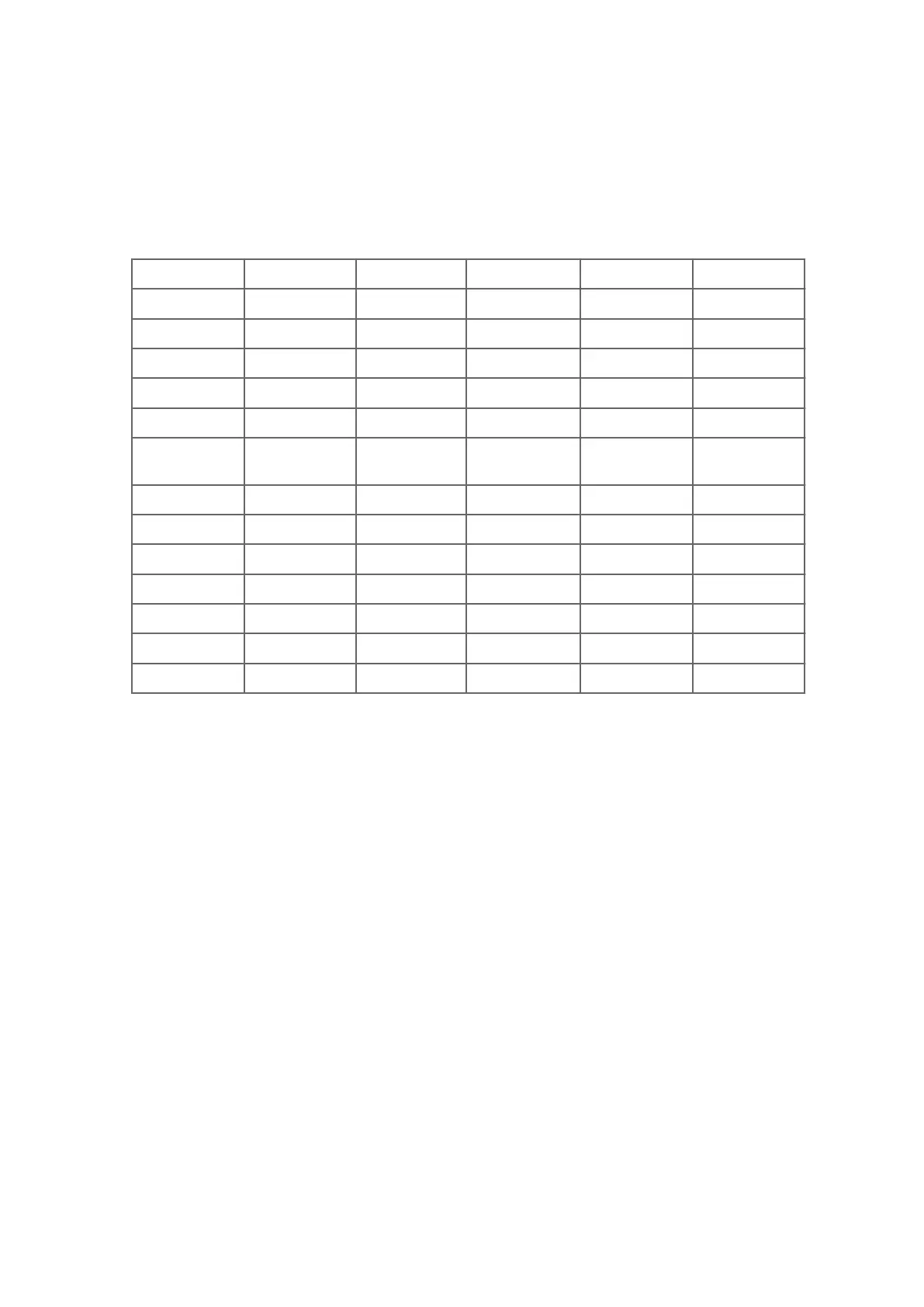
Table 25 Pinout for the MITEQ MFS–xx.xx–xx.xx–100K–xxMP Synthesizers
Ribbon Pin "D" Pin Function Ribbon Pin "D" Pin Function
1 1 Ground 2 14 Ground
3 2 +20 VDC 4 15 +20 VDC
5 3 +5.2 VDC 6 16 +5.2 VDC
7 4 Test Point 8 17 10 MHz (1)
9 5 TTL Alarm 10 18 1 MHz (8)
11 6
Phase
Voltage
12 19 1 MHz (4)
13 7 100 MHz (8) 14 20 1 MHz (2)
15 8 100 MHz (4) 16 21 1 MHz (1)
17 9 100 MHz (2) 18 22 100 MHz (8)
19 10 100 MHz (1) 20 23 100 MHz (4)
21 11 10 MHz (8) 22 24 100 MHz (2)
23 12 10 MHz (4) 24 25 100 MHz (1)
25 13 10 MHz (2) 26
-- --
Configure the DAFC pins:
• Pins 1 and 14 are ground, and are connected with wirewrap wire to the nearby ground
posts.
• Pins 2 and 15 are connected with a wirewrap wire to the +24 V posts, and pint 3 and 16
are connected with wirewrap wire to the +5 V posts.
• The Alarm on pin 5 is wired to the alarm post.
• Pins 7 through 13 and pins 17 through 25 all are signal pins, so we plug in a jumper for
each of these 16 pins.
• H3 and H4 are removed because we use pinmap uplink protocol.
• Remove H5
• Leave H1 on
In this example, we assume that we wish to control the STALO in 100 KHz steps from 5.1330
GHz to 5.1830 GHz. This can be done with the following setups from the Mb section:
Chapter 4 – RVP Hardware
79
 Loading...