Do you have a question about the Valhalla Scientific Alpha 4314 and is the answer not in the manual?
Provides an overview of the manual's content and scope for the Valhalla Scientific Model Alpha 4314.
Details the separation of the manual into 11 chapters, outlining the content of each chapter.
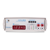
Describes the Valhalla Scientific Model Alpha 4314 Digital Igniter Tester and its primary uses.
Outlines critical safety precautions for operating the Alpha 4314, especially regarding battery charging.
Explains how to identify Valhalla Scientific instruments using a two-part serial number system.
Guides users on inspecting the unit for damage during unpacking and reporting issues.
Details the instrument's power source, battery, and charging requirements for the Model Alpha 4314.
Provides guidance on installing the Model Alpha 4314, including rack mounting options.
Lists the measurement ranges, resolution, test currents, and failsafe currents for the Alpha 4314.
Details the accuracy specifications for various measurement ranges of the Alpha 4314 igniter tester.
Specifies the temperature coefficient and operating/storage ranges for the instrument.
Provides details on display type, conversion rate, terminal configuration, and power for the Alpha 4314.
Lists the physical dimensions and weight of the Valhalla Scientific Alpha 4314.
Lists and describes optional accessories available for the Alpha 4314 Series Digital Igniter Testers.
Details various test lead options, including Kelvin lead sets and micro-probes for the Alpha 4314.
Covers interface options like BCD data output and the Model 1248 Dual-Limit Comparator.
Provides an overview of operating instructions for the Alpha 4314, including controls and connections.
Describes the front panel controls, including the power switch and range selection buttons.
Details components on the rear panel, such as the fuse holder and charging jack.
Explains the four-terminal configuration used for accurate resistance measurements.
Guides users on understanding the instrument's display readings and potential ambiguities.
Explains the proprietary failsafe current design that prevents excessive voltage or current delivery.
Describes the circuit that monitors battery voltage and indicates low battery status.
Explains the function of the range indicator LEDs on the display board.
Introduces the block diagram and proprietary nature of the instrument's design.
Provides guidance on resolving malfunctions by reviewing instructions and checking components.
Offers strategies for identifying the root cause of instrument problems before component replacement.
Outlines precautions and procedures for replacing faulty components to maintain accuracy.
References circuit descriptions and schematic diagrams for internal workings.
Explains the instrument's power supply, including battery operation and charging.
Details the circuitry responsible for generating a constant current for measurements.
Describes the transconductance amplifier circuit, including its patent and operation.
Explains the failsafe design features that limit current and voltage to prevent damage or hazard.
Details the process of analog-to-digital conversion and the components involved.
Explains the operation of the 7-segment LEDs and the ±1 LED for displaying readings.
Explains the function of the range indicator LEDs on the display board.
Lists the necessary test equipment, including precision resistors and voltage standards, for calibration.
Specifies the precision resistors required for calibrating different ranges of the Alpha 4314.
Mentions the required 4-Wire Lead Set for calibration procedures.
Specifies the voltage calibrator requirements for calibration accuracy.
Mentions the power supply requirement for calibration procedures.
Provides step-by-step instructions for calibrating the Alpha 4314 instrument.
Details the specific steps for adjusting the voltmeter calibration on the Alpha 4314.
Outlines the procedure for calibrating the full scale readings on the instrument.
Describes how to adjust the low battery indicator to ensure correct operation.
Explains how to check calibration results, including scale and linearity.
Details the process for checking the instrument's scale and linearity post-calibration.
Describes the procedure for performing a zero check on the instrument.
Provides step-by-step instructions for replacing the rechargeable batteries in the Alpha 4314.
Details the rear-mounted BCD interface connector and its pin functions for data output.
| Brand | Valhalla Scientific |
|---|---|
| Model | Alpha 4314 |
| Category | Test Equipment |
| Language | English |