XORK
I
NSTRIJCT
IONS
CIL I ND€R IfAD ATD VALVE
I.ECHAN
I
SM
CYL II{DER I€AD
REI,IOY
ING THE CYLINDER
T€AD
Clean +he outslde of l-he
gnglne
and
draln the
coolant.
Dlsconneci
fhe
rater hoses
flxed +o
ihe
cyllnder head and thernosiat
houslng.
Remove
the
al.
plpes
bettregn
alr fi
lier
and
turbocharger
and between +urbocharger
and lnlef
rnanlfold.
Loosen
ihe
screws of +he mounilng flange of ihe
+urbocharger
pressure
ol
I
plpe
and the lower
plpe
connec+or, then remove the
plpe.
Loosen
ihe
scrers of ihe turbocharger reiurn ol I
plpe
flange
and the louer
clanp,
fhen renove the
p
lpe.
Dlsconneci
ihe olDes of fhe fusl reservolr of
+he
Thgrn|osiart
devlce
(lf
assembled).
open
ihe connec+lng scr6*s of the overflov/
plpe
of ihe
InJec+ors, remove the
plpo
and dlsnoun+
+he lnJectlon
plpes,
0pen +he Injec+or
reialnlng nuts
and
renpve
the lnjeciors. Fli
protecilve plugs
ln the connectlon
polnts
ol
the {ue
I eou iomenl-.
open
fhe
connec+lng screr of +he lube oi I
plpe
leadlng
+o +he cyllnder
head and
the
plpe
jolnf
at the
lorer end, then redpve ihe
plpe
(Jll,
611
,
612t,
Open +he lnlei manlfold
flxlng screws, exhaus+
manlfold nuis,
+herrnosiat
houslng
scre{s
and
lronf
llfflng lu9 scrers
ond
rsmove
-the
parts
from ihe
cy I I
ndor
head.
open the
refalnlng nuts
ol thg
valve gear
cover
and renove +he
cover and
thg
breaiher
DlDe
(
309,51
t,411).
open +he valve
gear
reialnlng nu+s and bolf and
remove ihe
valve
gear.
Llfi
ihe
push
rods
off
of fhelr
Dos lf lons.
Loosen ihe cyllnder
head
flxlng
gcfexs
by iurn-
Ing them
tlrsl only
€boui 1/4 ot a
roiailon
ai
a ilme.
Renove +he screxs and dismolni th9
cyllnder
head. lf the
cyllnder head
is ilghfly
fltted,
d<r not tap a {edge bet{eon lhe
cyllnder
block
and head, slnce
thls
may damage
ihe
seallng l8ces.
REIIOV
ll,lc IHE VALVES
lf
you
Intend
io fl+ +he
sane valves back, mark
+hem
so fhat
you
can lnsiall +hen
In ihelr
orlg
Inal
pos
lt lons.
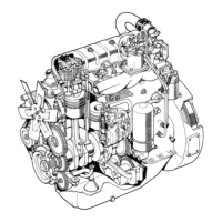
1. Ffx +he lock nut
(At6O
91t561 oI
sprlng
llftlng lever
In the valve
s+ud
(fryl
and
6-cyl
englnes
have
ihe
mlddle
valves.
ln +hls case flx
a hexagofl screw of
sul+able lengih).
Flx ihe valv€ sprlng
ftttlng lever
(8160
975f2)
on l-op of +he
valve sprlngs
and compress
fhe
sprlngs. Remove splli
col
lgfs, sPrlng
collars
and sprlngs
and
deiach lhe
valve.
CTCCKI
NG I}IE CYL I
NDER
IfAD
Removs
the carbon
deposl+
from
ihe exhaust
po-fs,
clean
the seallng
taceg and
liash
ihe
cyllnder hgad
caretu
lly.
Check the cyllnder head
for
posslble
cracks
ånd
other
danage.
2.
c.
t.
t.
1.
9.
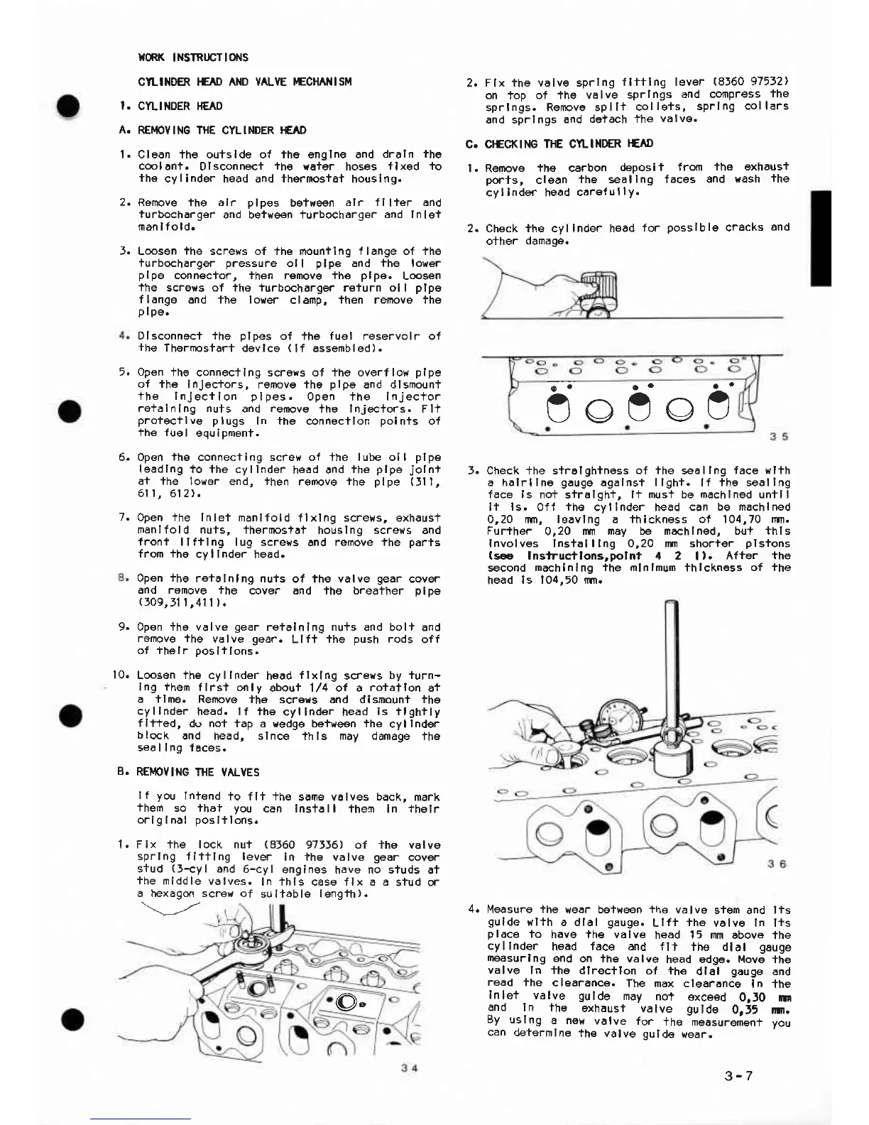
Check +he s+rolgh+n6ss
of ihe
seallng
tace wlth
a halrllne
gauge
agalnsi llght.
lf
ihe seallng
face is not
siralgh+,
l+ mus+ be machlned untll
It ls.0ff the cyllnder head can
be machlned
0,20 rin, leavlng a thlckness of 104,70
dm.
Further
0,20
rm rnay be machlned, bu+ thls
lnvolves lnstalllng 0,20 rm shorter
plsions
(s€
lnstructlons,pol nt
il
2
|
).
After the
second
machlnlng ihe mlnlmum
thlckness
of ihe
head
ls 104,50 im.
10.
the valvg
gear
cover
no studs
a+
a a
sTuo or
f4easuro the
wear be+ween the valve
siem and lis
gulde
wlfh
a dlal
gauge.
Llfi
iho
valv6 ln l+s
place
to
have lhe valve
head 15 mm above the
cyllnder
head tace and fll
ihe dlal
gauge
measurlng
end
on the valve
head edge. Move
-the
valve
ln fhe dlrec+lon
of +he
dlal
gauge
and
read
ihe
clearance.
The max clearönce
ln +he
lnlet
valve
gulde
may
no+
exceed
0,lO
m
and
In the
exhaust
valve gulde
0r55 ||m.
By
uslng
a ne},
valve
{or
+he
measurement
vou
can determlne
ih€ valve gulde
wear.
5o9oO
@"
3-7
 Loading...