4.
Grlnd the valye
agalnsi
lis sea+ xlih a flne
grlndlng pasie.
Check the con+act surfaces
rlth
tes+lng
co
lour.
5. Clean the cyllnder
head
and the valves of
grlnd
Ing resldues carefu
lly.
I
.
F ITTII{G TIf, VALVES
l. Check the
condlilon ot
the valve sprlngs. lf
nocessary, irfal
press
lhe sprlngs
ln å control
devlce,
for
pressure
see Technlcal
da+a,
poln+
valvos.
2.
Lubrlca+e
the
valve stems ulth enolne oll
and
place
ihe
valves
ln the correc+ örder ln ihe
cyl lnder head.
i. Flt
thg valve sprlngs and sprlng collars
In
place,
compress
ihe
sprlngs |rlih
flttlng lever
lAt6O 97552t and flt
spllt colle+s
In
place.
Af+er fltilng
lhe
valves ansure fhat the
split
col lets a.e corroct ly
posl+loned
by, for
example,
carefully tapplng
on ihe valve heads
rlih a
plåsilc
hanmer.
FITTING
THE Crl- tiFER
IEAD rO9, lll,
4ll
Ensure
fha'f the cyllnder head fixlng
studs
(no+
109) are
properly
ilghiened
to ihe cyl block
(50
ilo). Flt the
valvs +aooets
In thelr
Dosl
+
lons.
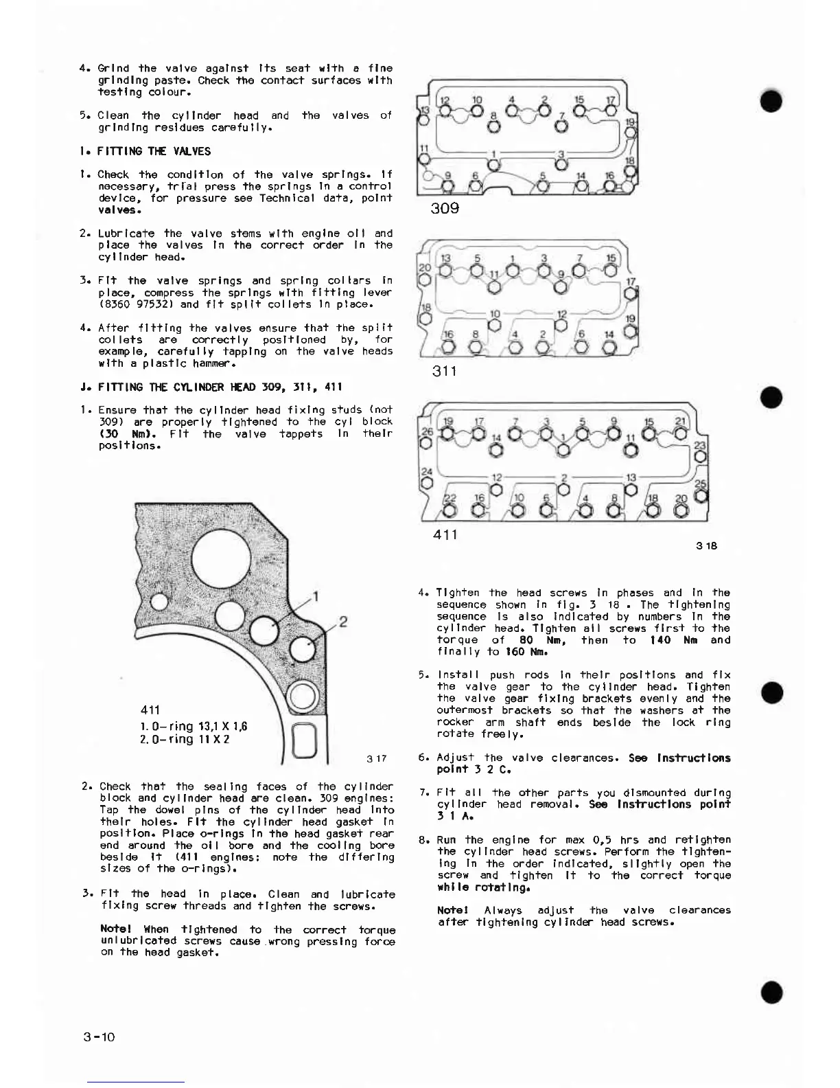
318
Tlgh+en ihe
head screws In
phasss
and In
lhe
sequence
shown
ln llg.
! 18. The
tlghtenlng
sequence ls also Indlca+ed by numbers ln
ihe
cyllnder
head. Tlghten all
gcrews
tlrs+ +o lh€
torque
of 80 Nn, then io
|
40 Nn and
f
Inölly
+o 160
Nn.
Insl-all
Dush
rods
ln
thelr
oosl+lons
and flx
ihe völve gear
io ihe
cyllnder head. Tlghten
ihe valve gear
flxlng
brackgts evenly and
lhe
ou+ermosf
brackeis so +hat the eashers ai
ihe
rocker
arm shalt ends
beslde
+he lock
rlnq
rotate
free lv.
J.
317
Check that
ihe
seallng faces of the cyllnder
block and
cyllnder
head
are clean. J09 englnes:
Tap the dowel
plns
of the cyllnder
head
Inio
thelr
holes. Flt the
cyllnder head
gasket
In
posltlon.
Place o-rlngs ln ihe
hsad
gaske+
rear
end around the ol
I bore
and ihe coollng boro
beslde ll
(4ll
englnas:
noie lhe dlfferlng
slzes of ihe o-rlngs).
Fli
fhe
head In place.
Clean and
lubrlcaie
flxlng
scrsw ihreads
and tlghten
+he screws.
Note
I }lhen ilghtengd
io +he
correci forque
unlubrlcated
screys
cause.yrong
presslng
force
on +he
head
gasket,
6. Adj ust ihe
polnt
J 2 C.
va lve
clearancos.
S€ lnsiructlo|ls
7. Flt all
+he oiher
parts you
dlsmounled
durlng
cyllnder head
renoval.
S9g lnstructlons
polnt
ltA.
8. Run
+he englne for max
0,5 hrs
and retlghien
'the
cyllnder
hgad screys. Parform
ihe ilghfen-
Ing
In
+he order indlca+ed,
sllgh+ly
open +he
screw and
+lghten li to fhe correct
iorque
rhl le rofatl
n9.
Nqtet Alrays
adjust +he valve clearances
afts' tlghtenlng cyl indq- head screxs.
309
311
411
411
l.
0- ring
13,1 X 1,6
2.
0-
ring
1l x 2
3-10
 Loading...