The lnJec+lon
pump
ls flxed
fo +he
goar
houslng
rllh ö
tlonge and s€cled rlth an O-rln9
(5).
The
punp
ls drlven by cronkshafl vla ldler
gear
and
pung geär
(6).
The InJectlon
pump
ls
connecied to ih€ englne lubrlcatlon sysfem
by
Deans ol
on oui€r
plpe
(4).
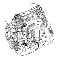
l. Pressurg
valve holder
2. Prossure
f. El6nen+
4. Conlrol
rod
5. Return
elemenf
plsion
6. Rol16r tappe+
7.
The
elenEnt
conslsts of a
plungEr
(4)
and a
cyllnder
(2)
vihlch have been tliied
to
€ach
o+her wlth a thouscndth-mllllrneire accuracy.
Due +o +hls
accuracy In flitlng +he elenent
should
alvays
b9 repleced as ö xhol9.
The cyllnder
of the elgn€ni
has
iro
borlngs:
lnlei
bore
(l)
ond
gulde
bore
(4)
ihrough
thlch
fha fuel ls dlreclod lnto +he
orgssure chamber.
0n the slde of the
plston
(5)
+here ls a long-
lludlnal
groove
(7)
and
a regulatlng rlm
(6)
rhlch
regulate
the amount of
fuel
lnJecied lnio
the cy llnders.
On
th6
head
of
the elerient
Dlslon
there ls also
a siarilng
g.@ve
(l)
r,hlch delöys the
InJ€c+lon tlmlng
by aboui 70...80
durlng
slort.
(Not€
thls Hhen
checklng the lnJectlon
tlmlng, seo lnstrucllons
ln
polnt
9
2 A'.
Thls
func+lon, ehlch
ls fully
auiomotlc, ls to
lmprove +he
englne
cold start characlerlsilcs.
lh6n
ihe
englne
stops
ihe
conirol rod turns thg
6lel€nt siartlng
grooye
so that li ls at ihe
cyllnder
gulde
hole.
Durlng
slarllng, atler
the lnjocilon pump
has
reached
a
certaln
spe€d,
the
governor
drors
fhe
control rod back
to
the
runn Ing
poslilon.
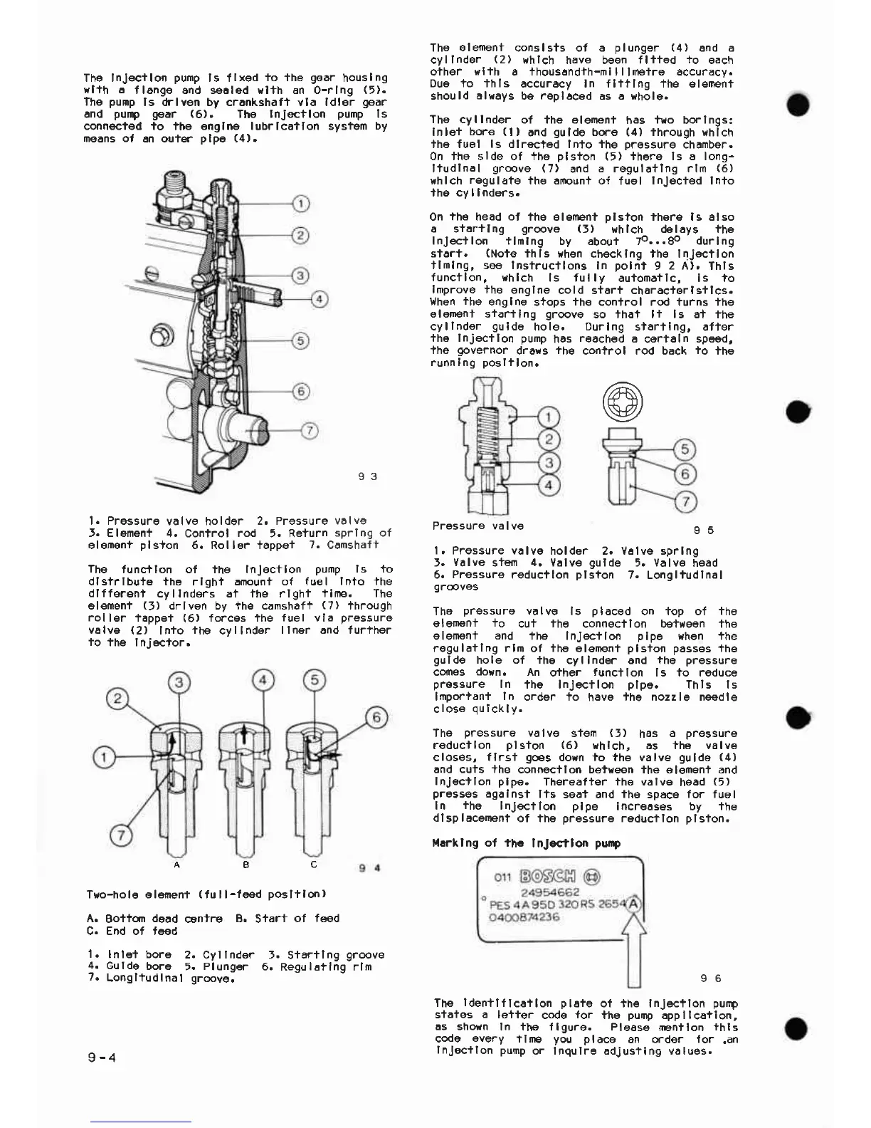
Pressure
va
lve
9 5
l. Pressure
yolvg
holder 2, V6lve sprlng
J.
Valve
stefl
4.
Valv€
gulde
5. Valv€
h€ad
6.
Pressurs
reducilon
plston
7.
Longliudlnal
ga@ves
The
pressuro
valve
ls
placed
on top of tho
glgmenl
+o
cui
ihe
conngcllon between lhe
elemen+
and
the InJ€ctlon
plpe
when lhe
regulatlng rlo
ol
the elenent
plsfon passes
the
gulde
hole of ihe
cyllnder and ihe
pressure
cdnss
dorn.
An
crther
tunctlon
ls to reduce
pr€ssure
In
the InJecilon
plpe.
Thls
ls
lmDor+ani
ln
order lo
have
the nozzle needle
close au
i
ck lv.
The
pressure
valvg
stern
(i)
has
a
pressure
reducllon
plston
(6)
rhlch, as the valve
closes,
flrsf
9€s
dorn
io
the valve
guld6
(4)
and cuts +he
conngctlon betreen ihe elemenl and
lnJEc+lon
plpe.
Ther€after the valva
head
(5)
presses
agalnst
lts
sga+ and
ihe
space
for fuel
In
ihe
InJectlon plpe
Increoses by
the
dlsplacenent
of the
pressure
reduqflon
plsfon.
lllrtlng ot ihc
I nJoctlon
purp
@
Th€
ldentlflcoflon pl€te
of +h€ Injecflon
purp
sfåtes
a
lo+ter
codg
for
the
puDp
appllcatlon,
:L,*ä";" J,R'Ji,l'?,
""i'lT'
#::'%.'1::
g_4
lnJoc+lon pump
or Inqulre Edjus+lng våtues.
93
spr I ng of
Coms haf
l-
The
tunqllon of the InJectlon
punp
ls +o
dlstrlbute the rlght anounf of fuel
lnto the
dlfferent
cyllnders at the rlghi
ilne. The
elemen+
(5)
drlven by ihE camshafi
(7)
lhrough
roller
tappei
(6)
forces the
fuel vla
pressure
valva
(2)
lnio
ihe
cvllndor
llner and lurlher
io
the I nJec+or.
A8C
T!,o-hole eleneni
(
fu I l-te€d
posltlo.r)
Boiim
dead
contre
B.
End of teed
In le+ bore
2. Cyllnder
Gulde
bore
5.
Plung€r
Longltudlnal groove.
Sfart
of
f€ed
t.
Starilng
groove
6. Regu
l6t
Ing rlm
 Loading...