EasyManua.ls Logo

Vanair AIR N ARC RELIANT 150 Series User Manual

Vanair AIR N ARC RELIANT 150 Series
92 pages
To Next Page IconTo Next Page
Page #1 background imageLoading...
Page #1 background image
ALL-IN-ONE POWER SYSTEMS
®
WELDER • GENERATOR • AIR COMPRESSOR • BATTERY BOOSTER
OPERATION MANUAL & PARTS LIST
©2014 Vanair Manufacturing, Inc.
All rights reserved
090051-OP_r0
Effective Date:
2-2014
NOTE
Read this manual before installing,
operating or servicing this
equipment. Failure to comply with
the operation and maintenance
instructions in this manual WILL
VOID THE EQUIPMENT WARRANTY.
NOTE
Use only Genuine Vanair Parts.
Inspect and replace damaged
components before operation.
Substituting non-Vanair
components WILL VOID THE
COMPRESSOR WARRANTY!
Vanair Manufacturing, Inc.
10896 West 300 North
Michigan City, IN 46360
Phone: (219) 879-5100
(800) 526-8817
Service Fax: (219) 879-5335
Parts Fax: (219) 879-5340
Sales Fax: (219) 879-5800
www.vanair.com
NOTE
Making unauthorized modifications to
the system components WILL VOID THE
WARRANTY!
Always inform Vanair Manufacturing,
Inc. before beginning any changes to the
Air N Arc system.
KEEP THE MANUAL
WITH THE VEHICLE

Table of Contents

Question and Answer IconNeed help?

Do you have a question about the Vanair AIR N ARC RELIANT 150 Series and is the answer not in the manual?
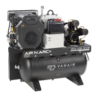
Vanair AIR N ARC RELIANT 150 Series Specifications

General IconGeneral
EngineKohler CH440
Output Current150 Amps
Engine Power14 HP
Fuel TypeGasoline
Duty Cycle100% @ 150 Amps
ModelReliant 150
Power Output150 Amps
Power SourceEngine Driven
Output Power150 Amps

Summary

VANTAGE WARRANTY

WARRANTY

WARRANTY CLAIM PROCEDURE

Process for submitting and processing warranty claims.

SECTION 1: SAFETY

1.1 GENERAL INFORMATION

Overview of safety responsibilities and manual usage.

1.2 DANGERS, WARNINGS, CAUTIONS, AND NOTES

Definitions of safety alert symbols and their meanings.

1.3 INTERNATIONAL SAFETY SYMBOL

Explanation of the universal warning symbol and its importance.

1.4 ARC WELDING HAZARDS

Hazards associated with arc welding processes.

1.5 ENGINE HAZARDS

Potential dangers related to the engine system.

1.6 COMPRESSED AIR HAZARDS

Risks associated with compressed air systems.

1.7 ADDITIONAL SYMBOLS FOR INSTALLATION, OPERATION AND MAINTENANCE

Symbols used for specific operational guidance.

1.8 CALIFORNIA PROPOSITION 65 WARNINGS

Specific warnings regarding chemicals known to cause birth defects or cancer.

1.9 PRINCIPAL SAFETY STANDARDS

List of relevant safety standards and codes.

1.10 EMF INFORMATION

Information on electromagnetic fields and their potential effects.

1.11 SAFETY DECALS

Location and importance of safety decals on the equipment.

1.12 DISPOSING OF MACHINE FLUIDS

Proper procedures for disposing of machine fluids.

SECTION 2: SPECIFICATIONS

TABLE 2A: SPECIFICATIONS

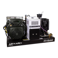
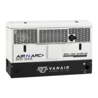
Detailed technical specifications of the Air N Arc 150 system.

TABLE 2B: UNIT WEIGHT AND DIMENSIONS

Physical dimensions and weight of the unit.

SECTION 3: INSTALLATION

3.1 MACHINE PACKAGE RECEIPT/INSPECTION

Procedures for inspecting the machine upon receipt.

3.2 MACHINE PACKAGE PREP

Steps to prepare the machine package before installation.

3.3 SERVICE BODY PREP

Preparation steps for the service body.

3.4 MACHINE PACKAGE MOUNTING

Guidelines for securely mounting the machine package.

SECTION 4: OPERATION

4.1 GENERAL INFORMATION

Introduction to the Air N Arc 150 Series system operation.

4.2 ENGINE START-UP AND SHUTDOWN PROCEDURE

Step-by-step guide for starting and stopping the engine.

4.3 ENGINE THROTTLE CONTROL FUNCTIONS

How engine speed is controlled based on system demands.

4.4 OPERATING THE WELDER

Instructions for using the welding function of the machine.

4.5 OPERATING THE GENERATOR

Guidelines for operating the AC generator.

4.6 OPERATING THE AIR COMPRESSOR

Procedures for operating the air compressor system.

4.7 EXTREME CONDITION OPERATION

Special considerations for operating in extreme environments.

SECTION 5: MAINTENANCE

5.1 GENERAL INFORMATION

Importance of a strict maintenance program for longevity.

5.2 ROUTINE MAINTENANCE SCHEDULE

Overview of the recommended maintenance schedule.

5.3 MAINTENANCE SCHEDULE

Detailed schedule of tasks and intervals for maintenance.

5.4 REPLACEMENT PARTS

Information on how and where to purchase replacement parts.

5.5 PARTS REPLACEMENT AND ADJUSTMENT PROCEDURES

Detailed procedures for replacing parts and making adjustments.

5.5.1 ADJUSTING THE ENGINE SPEED

Instructions for adjusting engine speed.

SECTION 6: TROUBLESHOOTING

6.1 GENERAL INFORMATION

Introduction to troubleshooting common problems.

6.2 TROUBLESHOOTING GUIDE

Guide listing faults, causes, and corrective actions.

SECTION 7: ILLUSTRATED PARTS LIST

7.1 PARTS ORDERING PROCEDURE

How to order parts, including necessary information.

7.2 COMPRESSOR

Illustrated parts breakdown for the compressor assembly.

7.3A FRAME ASSEMBLY (ALL 10 GALLON MODEL OPTIONS)

Illustrated parts for the 10-gallon frame assembly.

7.3B FRAME ASSEMBLY (ALL 30 GALLON MODEL OPTIONS)

Illustrated parts for the 30-gallon frame assembly.

7.3C FRAME ASSEMBLY (ALL SKID-MOUNT MODEL OPTIONS)

Illustrated parts for the skid-mount frame assembly.

7.4 ENGINE AND DRIVE PARTS (1 OF 2)

Illustrated parts list for engine and drive components (part 1).

7.4 ENGINE AND DRIVE PARTS (2 OF 2)

Illustrated parts list for engine and drive components (part 2).

7.5 BELT GUARD ASSEMBLY

Illustrated parts breakdown for the belt guard assembly.

7.6 ELECTRICAL SYSTEM

Illustrated parts list for the electrical system components.

7.7 CONTROL ASSEMBLY (30 GALLON AND SKID-MOUNT REMOTE OPTIONS)

Illustrated parts for the control assembly.

7.8A AIR TANK (ALL 10 GALLON MODEL OPTIONS)

Illustrated parts for the 10-gallon air tank.

7.8B AIR TANK (ALL 30 GALLON MODEL OPTIONS)

Illustrated parts for the 30-gallon air tank.

7.9 DECAL LOCATIONS

Diagrams showing the location of various decals on the unit.

7.10 WIRING DIAGRAM

Schematic showing electrical connections and components.

7.11A INSTALLATION AND DIMENSIONS - 10 GALLON TANK MOUNT

Dimensional drawings for 10-gallon tank mount installation.

7.11B INSTALLATION AND DIMENSIONS - 30 GALLON TANK MOUNT

Dimensional drawings for 30-gallon tank mount installation.

7.11C INSTALLATION AND DIMENSIONS - SKID-MOUNT

Dimensional drawings for skid-mount installation.

7.12 HOSE INSTALLATION GUIDE

Best practices for installing hose assemblies.

Related product manuals