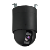
CCID1445, IP High-Speed Dome Camera, D/N
Package contents
Camera base
Dome module
Template
3 anchors
3 screws
Video cable
2 GB MicroSD card (in box)
Installation instruction
Utilities CD (including software and documentation)
Target readers
This installation instruction is only intended for use by
installers who have an adequate working knowledge of video
systems!
Installation must be performed by qualified service personnel
in accordance with all local codes.
Safety
General safety precautions
Read the general safety precautions before
installing/configuring/operating the device.
Keep this document for reference.
Always pass this document on together with the product.
Please take into account any additional country-specific,
local laws, safety standards or regulations concerning
installation, operation and disposal of the product.
Ensure that the safety wire (located in the dome base) is
engaged.
Use only spare parts and accessories that have been
approved by the manufacturer.
Transport
Keep the packaging material for future transportation.
Do not expose the device to mechanical vibrations or
shocks.
Installation
Refer to a qualified electrician for installation.
The environmental conditions recommended by the
manufacturer must be observed. See "Technical data".
Do not operate the device close to sources of powerful
electromagnetic radiation.
The device should only be used for indoor applications.
The mounting surface must be solid and non-
combustible.
Danger of electrical shock/fire hazard/damage to the
device due to incorrect connection
Connect the device only to a power source that complies
with SELV requirements and with the Limited Power
Source requirements to EN 60950-1.
Connect the equipment to 24 V AC UL listed Class 2
Power Supply or PoE+.
Service and maintenance
Do not attempt to service or modify this device yourself.
Refer this work to qualified service personnel.
Do not use liquid cleaners or sprays that contain alcohol,
spirit or ammonia.
Details for ordering
1/4" IP Speed Dome, Colour, 28 x
Optical Zoom, 24 V AC, PoE+
1/4" IP Speed Dome, D/N, 36 x
Optical Zoom, 24 V AC, PoE+
Installation
Step 1: Mounting
1. Mark the mounting holes for the dome camera using the
drilling template.
2. Drill the mounting holes and insert the wall plugs.
3. If necessary, cut a space for the supply cables at the
mounting location.
4. If required, remove the knockout for cable entry.
5. Pass the cables into the housing.
6. Attach the unit to the mounting surface using the screws
included in the delivery.
7. Connect the support wire (3) to the hook (2) of the dome
base (1).
Step 2: Connection
Alarm input
Connect the control input to the terminals GND and AL IN (7).
IP interface
Connect the IP cable for configuration and operation via
Ethernet to the RJ45 connector (9).
BNC connector
If required, connect the BNC extension cable (14) to the BNC
connector (8).
Power supply
Select one of the following options:
24 V AC:
Connect the 24 V AC cables to the terminals 24VAC.
PoE:
Connect the network cable to the RJ45 terminal (9) using
a PoE+ compatible hub or switch.
Step 3: Mounting the camera module
To lock the dome module (4) to the camera base (1), line up
the notch (15) to the right arrow on the label (16), then turn
the dome module to the right with both hands until the notch
lines up to left arrow.
Start-up procedure
When powered up, the camera will perform a brief routine
during which it checks its function and will then go to its start
position.
Install the remote software onto your PC, following the
description in the "Readme" file on the CD.
Access the IP camera.
Default settings:
IP address: 192.168.0.10
User: admin
Password: admin
Set the parameters and back up the file.
Detailed information on parameter setting can be found in the
operator manual on CD.
Firmware check/update
If you require further information, please contact our support
team:
www.service.vanderbiltindustries.com
Technical data
D/N: 530 TV lines
Col.: 480 TV lines
MJPEG: D1 (720 x 576) / VGA
(640 x 480) / QVGA
(320 X 240): 25 ips (PAL)
MPEG-4: D1 (720 x 576) / VGA
(640 x 480) / QVGA
(320 X 240): 25 ips (PAL)
H.264: D1 (720 x 576) / VGA (640 x
480) / QVGA
(320 X 240): 25 ips (PAL)
MJPEG / MPEG-4 /
H.264 (triple encoding)
DN28: Color 1.0 lux (F1.6; 1/50 s)
B/W 0.01 lux (F1.4; 1/3 s)
DN36: Color 1.4 lux (F1.6; 1/50 s)
B/W 0.01 lux (F1.4; 1/3 s)
MicroSD card, up to 32 GB
TCP/IP, UDP, HTTP, HTTPs,
SMTP, SNMP, DNS, DHCP, NTP,
ARP, ICMP, FTPc, FTPs, DDNS,
RTSP (RTP, RTCP),
IGMP v3, UPnP,
CIFS, NFS, IEC802.1x, ONVIF
Internet Explorer 6.0 (Service Pack
2 or above) / Safari / Mozilla
FireFox
24 V AC ± 10 %, 50 Hz; PoE+
Environmental
operating
temperature
0 – 50 °C
(-30 to +50 °C with suitable
weatherproof housing)
Disposal
All electrical and electronic products should be
disposed of separately from the municipal
waste stream via designated collection facilities
appointed by the government or the local
authorities.
 Loading...