EasyManua.ls Logo

vanEE 41303 - User Manual

vanEE 41303
4 pages
Print Icon
To Next Page IconTo Next Page
Loading...
CAUTION
Failure to comply with the following can cause erratic operation of the control and/or unit:
Never install more than one main wall control per ventilation unit.
Keep control low voltage wiring at least 1 foot (305 mm) away from motors, lighting balast, light dimming circuit
and power distribution panel. Do not route control wiring alongside house power wiring.
Ensure the wires are securely connected.
Unplug the ventilation unit.
VC0217
VC0219
Unscrew the screw located on the
underside of the wall control.
Separate the front module from the
mounting plate by lifting its bottom
part.
12V D- D+ Gnd
Strip the end of the cable to access
the 4 wires (about 3"). Strip the end
of each wire (about 1/4"). Connect the
wires to the terminals, regardless of
the wire color. Note which wire color
has been chosen for each terminal.
VC0218
Install the front module on the
mounting plate. Fix both parts by
screwing the screw on the underside
of the wall control.
Be careful not to pinch wires when reinstalling the
front module on the mounting plate.
CAUTION
Plug the ventilation unit in power source.
This control is compatible with all AI and N series units.
VC0245A
PRELIMINARY SETTINGS
VC0246A
Set the Language and the Day and time screens following your preferences.
23840 rev. 02
Perform the electrical connection to the terminal connector of
the unit, as shown below. For more details, refer to the
installation manual of the ventilation unit.
12V D- D+ Gnd
VC0232
NOTE: To avoid miswiring, refer to the notes taken at step
to match the wire color with the right terminal.
W
ALL CONTROL REAR VIEW
NOTE: If the control is to be installed in an electric box, do
not perform steps 3 and 4.
INSTALLATION AND USER GUIDE FOR ADVANCED TOUCHSCREEN CONTROL
N
EE PART NO. 41303 VENMAR PART NO. 41403
READ AND SAVE THESE INSTRUCTIONS
The illustrations in this document are generic; your control appearance may be slightly different from the ones shown.
Electrical wiring must be done by qualified personnel in accordance with all applicable codes and standards.
Before connecting wires, unplug the unit or switch power off at service panel and lock service disconnecting
means to prevent power from being switched on accidentally. Always wear safety glasses and gloves while
performing these instructions.
WARNING
!
VC0255
Using the mounting plate, mark the
hole opening and screw locations at
the desired height on the wall.
VC0244A
Ø 3/16", typ.
Cut the hole opening using the mark
previously drawn (1/8" outside the
mark is recommended). Drill both
screw holes (3/16" Ø) in wall and
insert the wall anchors (included).
Fix the mounting plate to the wall using the screws provided.
Question and Answer IconNeed help?

Do you have a question about the vanEE 41303 and is the answer not in the manual?

Overview

This document describes the Advanced Touchscreen Control device, specifically models VANEÉ PART NO. 41303 and VENMAR PART NO. 41403. It serves as a user manual providing installation, usage, maintenance, and troubleshooting information.

Function Description

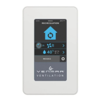
The Advanced Touchscreen Control is a sophisticated interface designed to manage ventilation systems. It allows users to control various aspects of their ventilation unit, including operating modes, fan speed, scheduling, and humidity settings. The device features a color touchscreen display for intuitive interaction and provides real-time feedback on the system's status. It is designed to be compatible with all AI and N series units.

Important Technical Specifications

The manual emphasizes several critical technical specifications and warnings related to installation and operation:

  • Electrical Wiring: All electrical wiring must be done by qualified personnel in accordance with all applicable codes and standards. Before connecting wires, unplug the unit or switch power off at the service panel and lock service disconnecting means to prevent power from being switched on accidentally. Always wear safety glasses and gloves while performing these instructions.
  • Ventilation: Failure to comply with the following can cause erratic operation of the control and/or unit:
    • Never install more than one main wall control per ventilation unit.
    • Keep control low voltage wiring (at least 1 foot (305 mm) away from motors, lighting ballast, light dimming circuit and power distribution panel).
    • Do not route control wiring alongside house power wiring.
    • Ensure the wires are securely connected.
  • Temperature Range: The temperature displayed on the Advanced Touchscreen Control wall plate may vary by 9°F (5°C) (more or less) compared to the inside temperature since the temperature sensor is located inside the unit. This is to ensure a reading that optimizes Virtuo Air Technology™ algorithms.

Usage Features

The Advanced Touchscreen Control offers a wide range of usage features accessible through its touchscreen interface:

  • Operating Modes: The control supports multiple operating modes, including:
    • Recirculation: Likely for internal air circulation.
    • Smart: An intelligent mode that automatically adjusts settings based on environmental conditions.
    • Continuous: Provides continuous ventilation.
    • Intermittent: Allows for scheduled or periodic ventilation.
    • Turbo: Boosts ventilation for a set period (e.g., 1 hr, 2 hr, 4 hr).
    • Away: Optimizes ventilation when the occupants are away.
  • Scheduling: Users can create and edit schedules (SCHEDULE A, SCHEDULE B) to automate ventilation based on specific days and times. The schedule editor allows for setting daily schedules.
  • Fan Speed Control: The device allows for adjustment of the blower speed.
  • Humidity Control: Features to enable/disable humidity function and adjust the set point.
  • Settings Menu: Access to various settings for customization.
  • Language Selection: The control supports multiple languages, including English, Français, and Español.
  • Time and Date Setting: Users can set the current time (AM/PM format) and date.
  • Current Mode Indicator: The display clearly indicates the current operating mode.
  • Error Indication: The device will display if an error occurs, and provides access to information regarding the error.
  • Temporary Modes: Allows for setting temporary modes.
  • RH Set Point Display: Displays the relative humidity set point.
  • Navigation Keys:
    • >: To access next screen.
    • <: To access previous screen.
    • : To confirm.
    • X: To exit screen without saving.
    • i: To get more information on the action(s) to perform on the corresponding screen.

Maintenance Features

The manual provides guidance on installation and troubleshooting, which indirectly relate to maintenance:

  • Installation Steps:
    1. Strip the end of the cable to access the 4 wires (about 3").
    2. Strip the end of each wire (about 1/4").
    3. Connect the wires to the terminal block, regardless of the wire color. Note which wire color has been chosen for each terminal.
    4. Unscrew the screw located on the underside of the wall control.
    5. Separate the control module from the mounting plate by lifting its bottom part.
    6. Cut the hole opening in the wall for the module, ensuring it is drawn tightly (1 7/8" outside the mark is recommended). Drill two screw holes (3/16" Ø) in the wall and insert the wall anchors (included).
    7. Fix the mounting plate to the wall using the screws provided.
    8. Install the front module on the wall plate by screwing the screw on the underside of the wall control.
    9. Perform the electrical connection to the terminal connector of the unit, as shown. For more details, refer to the installation manual of the ventilation unit.
  • Troubleshooting Guide: The manual includes a comprehensive troubleshooting section to address common issues:
    • Problem: The screen is not powered.
      • Possible Cause(s): The ventilation unit is not powered; Miswiring/Damaged wire; Contact between wires; The connector J15A is not connected properly; The wall control is not operational or defective.
      • Solution(s): Plug the ventilation unit; Check wall control wiring; Check J15A connector connection; Check if it uses the same isolated power circuit as the one on the electronic board; Replace the electronic assembly.
    • Problem: The screen is powered but displays error 50.
      • Possible Cause(s): Miswiring/Broken wire.
      • Solution(s): Check wall control wiring; Replace the electronic assembly.
    • Problem: The touch screen does not work for all the keys.
      • Possible Cause(s): Defective control.
      • Solution(s): Replace the electronic assembly.
  • Connection Verification: The manual advises to verify the connection, especially when an error is reported, and to refer to the notes taken at step ⑤ to match the wire color with the right terminal.

The document emphasizes the importance of professional installation and adherence to safety guidelines to ensure proper functioning and longevity of the Advanced Touchscreen Control.

vanEE 41303 Specifications

General IconGeneral
BrandvanEE
Model41303
CategoryController
LanguageEnglish

Related product manuals