Do you have a question about the Varex Imaging Claymount AmpMC 3-field Series and is the answer not in the manual?
Provides contact details for Varex Imaging Nederland B.V. and distributors for support.
Details product compliance with EU directives and explains document symbols used.
Lists technical abbreviations and general safety warnings for product usage.
Lists standard package contents and optional accessories for the AmpMC.
Defines intended use, provides an overview, explains operation, and lists classifications.
Outlines usage limits, contraindications, and detailed technical specifications of the AmpMC.
Details installation requirements, general guidance, and LED status checks.
Describes generator switch off check and necessary recurrent testing before patient use.
Covers mains isolation, safety measures, cleaning, and disinfection procedures.
Details steps for troubleshooting, including cable exchange or AmpMC replacement.
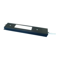
Shows mechanical layout and details generator interface connection pin assignments.
Explains DIL-switch settings for sensitivity, polarity, reset, exposure, and field selection.
Covers plug pinout assignments and outlines quality assurance requirements for the system.
Information on safe disposal, ESD precautions, and EMC compatibility.
Details deviations, allowances, precautions, emissions, and immunity compliance.
Describes the product label and explains various symbols found on the AmpMC device.
| Manufacturer | Varex Imaging |
|---|---|
| Series | Claymount AmpMC 3-field Series |
| Category | Amplifier |
| Number of Fields | 3 |
| Type | Image Intensifier |