Installation, Operating & Maintenance Instructions
Series 650 DN 100-250 (I.D. 4“ - 10”), CC-Link
VAT Vakuumventile AG, CH-9469 Haag, Switzerland
Tel +41 81 771 61 61 Fax +41 81 771 48 30 CH@vatvalve.com www.vatvalve.com
280672EB
2010-12-15
63/94
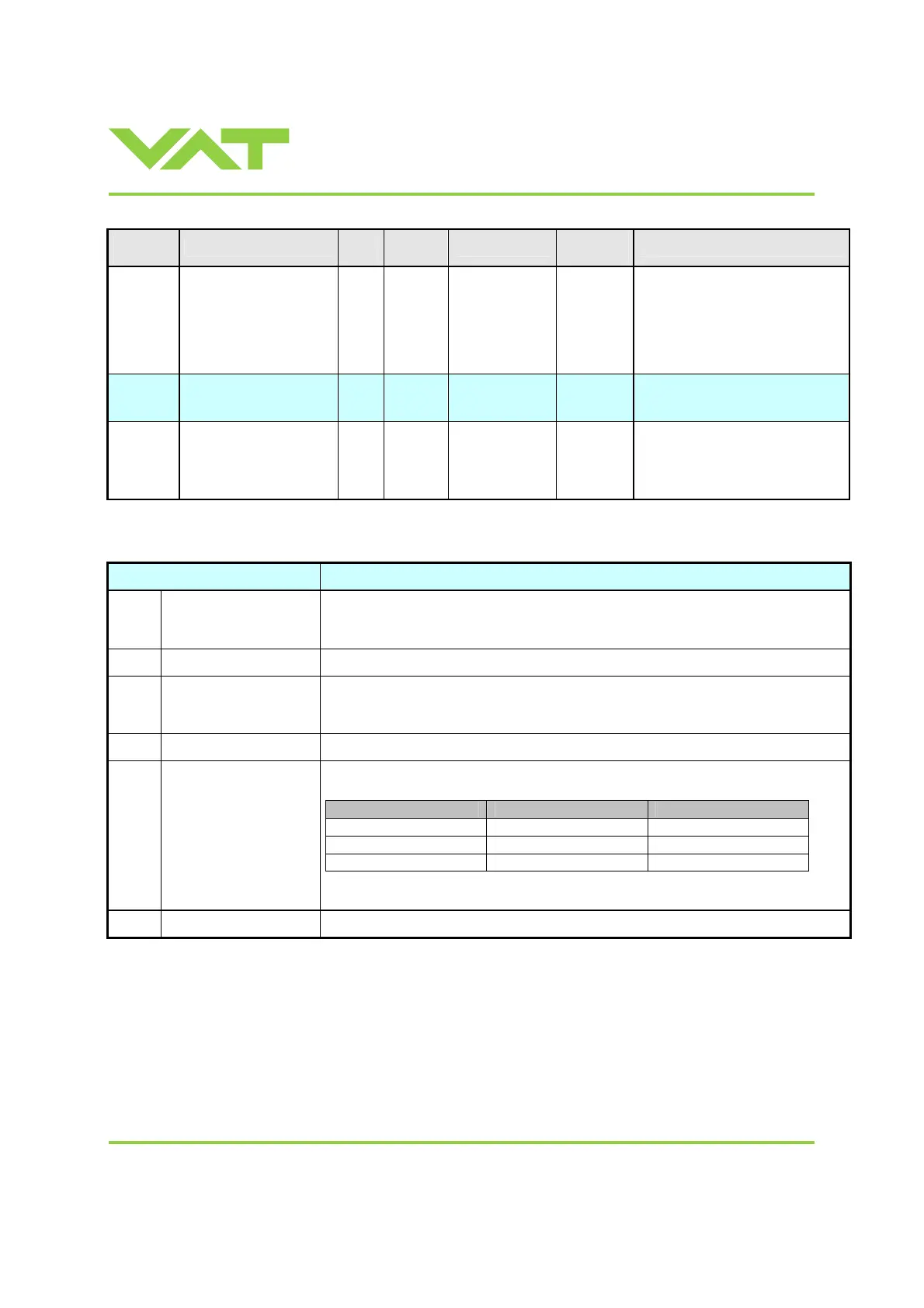
Signal
Type
Name
Start
Word
Byte
Length
Data Type
Valid
Range
Description
Signal
CLUSTER VALVE
FREEZE ADDRESS
SETPOINT
18 1 unsigned integer 0..254
Select a valve that should be frozen.
0 : master
1.. 254 : slave
Note: Only valid if bit FREEZE DATA
VALID is set
Bitmap
CLUSTER VALVE
FREEZE CONTROL
SETPOINT
19 1 boolean array
See bitmap table below
Signal
CLUSTER VALVE
MONITORING ADDRESS
SETPOINT
20 1 unsigned integer 0..254
Select a valve that should be
monitored.
0 : master
1..254 : slave
1) To adjust range refer to chapter: «Range of pressure and position values»
GENERAL CONTROL SETPOINT bitmap table:
Bit Description
0 ZERO
0 = No Operation
1 = ZERO adjust, the actual pressure signal is set to internal pressure 0. The valid range for
adjustment is limited to -1.4V…+1.4! Otherwise the sensor must be adjusted!
1
NOT USED (reserved)
-
2 PING PONG TX BIT
PING PONG TX BIT transmitted from the master (PLC), is used to check the loop "master PLC -
VAT station". See chapter: 3.11.9
Communication and timing control between Master
(PLC) and Station (Valve)
3
NOT USED (reserved)
-
4
ACCESS MODE LOCKED
Note: Access mode switching, only in remote mode possible (Host PLC).
Start mode Access mode locked bit End mode
local Set bit: 0Æ1 locked
locked Reset bit: 1Æ0 remote
remote Set bit: 0Æ1 locked
5-7
NOT USED (reserved)
-

 Loading...


