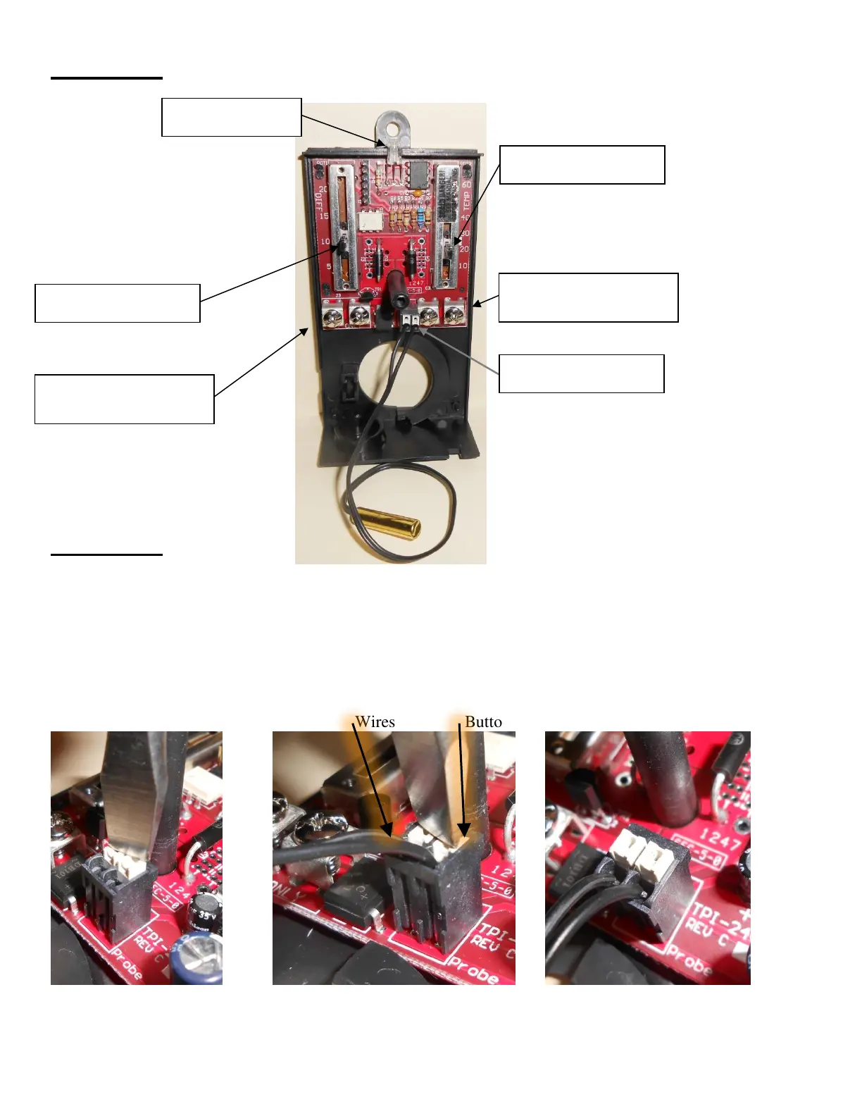
Diagram 4
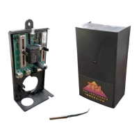
Diagram 5
Inserting the probe wires
5.A – Position tool (such as screwdriver) on top of white buttons
5.B – Push Down on white buttons and push wires Down into black holes in top of connector
(This can also be done one side at a time)
5.C – Tug on each wire to make sure they don’t move easily
5.A Buttons up 5.B Buttons down, Wires pushed down 5.C Buttons up, Wires tight
Wires Buttons
Revision 1.1
Optional 24V Power
Connection Screws