10
VFLPG/VFL/VTL/VRA
UWAGA !
Płytka PCB jest pod napięciem, kiedy nagrzewnica jest podłączona do zasilania.
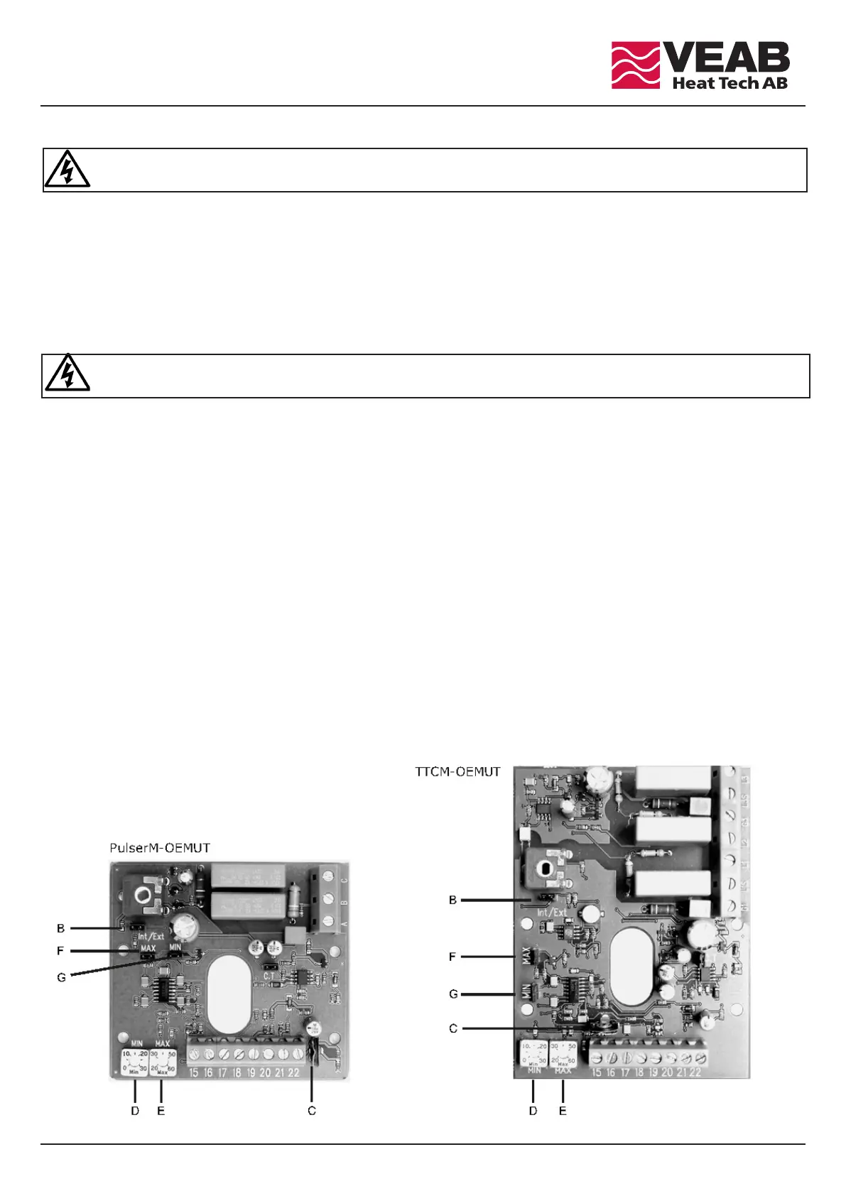
B = Zworka (Int/Ext) musi być zwarta.
C = Potencjometr dostrojczy ustawiony jest fabrycznie. Nie regulować!
D = Ustawnienie wartości zadanej dla ograniczenia temp. minimalnej.
E = Ustawnienie wartości zadanej dla ograniczenia temp. maksymalnej.
F = Zworka (MAX) musi być ZWARTA, aby aktywować funkcję ograniczenia temp. MAX.. OTWARTA w celu dezaktywacji funkcji.
G = Zworka (MIN)musi być ZWARTA, aby aktywować funkcję ograniczenia temp. MIN. OTWARTA w celu dezaktywacji funkcji.
Czerwona dioda przy zasilaniu 1 i 2 -fazowym lub dwie czerwone diody przy zasilaniu 3-fazowym wskazują, że elementy grzewcze są aktywne.
WARNING !
e PCB is at mains voltage level when the heater is connected to mains.
B = Jumper (Int/Ext) must be SHORTED.
C = Trim potentiometer set at manufactoring. Do NOT adjust!
D = Set point adjustment for MIN. temperature limitation.
E = Set point adjustment for MAX. temperature limitation.
F = Jumper (MAX) must be SHORTED to activate MAX. temperature limitation function. OPEN jumper deactivates the function.
G = Jumper (MIN) must be SHORTED to activate MIN. temperature limitation function. OPEN jumper deactivates the function. A red LED, at
1 and 2 phase supply, or two red LEDs, at 3 phase supply, indicates that the heating elements are activated.