7
VFLPG/VFL/VTL/VRA
Installation
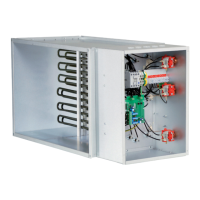
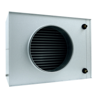
1. Heater VFLPG/VFL/VTL is designed for installation in duct systems. Heater VRA is designed for installation in a
ventilation device.
2. e direction of air through the heater must follow the air ow arrow on the heater.
3. e heater may be installed in a horizontal or a vertical duct, with the junction box to the side. Installation with the
junction box above or below is NOT allowed.
4. Inlets into rooms must be covered by a xed grill or air inlet unit that prevents the heating elements from being
touched in the case a protective grill is not installed on the heater.
5. A warning text regarding not covering the heater should be placed next to the outlet air opening.
6. e minimum distance to duct bends, dampers, lters etc. must be at least the same as the diagonal length of
the heater, i.e. the measurement from corner to corner of the heater’s duct section. Otherwise there is a risk for
irregularities in the air stream through the heater, which may trigger the overheat protection.
7. e heater may be insulated in accordance with applicable regulations for ventilation ducts/ventilation devices.
e insulation must consist of reproof insulation material. e insulation may not cover the lid as the rating
plate and warning sign must be visible and the lid must be accessible for opening. e heater must be accessible for
replacement and inspections.
8. e distance from the heater’s metal surface to wood or other ammable material may NOT be less than 100 mm.
Maintenance
1. In normal situations there is no need for maintenance. A periodic control of functions and re-tightening of power
supply connections must be carried out at least once per year.
2. To maintain isolation in the heating element, the power stage must be connected and run for 24h at least every 3
months.
Overheating
e heater contains at least two overheating protections (of which at least one is reset manually). If the overheating
protection that is reset manually is triggered, the following must be taken into consideration:
1. Cut o the power supply.
2. e heater’s lid may only be opened by a qualied technician.
3. oroughly investigate the cause for the overheating protection being triggered.
4. When the fault has been rectied, the overheating protection may be reset.
Trouble-shooting
- MTEM / -MTEML
• Check that the sensor is of the correct type and that its termination is made correctly.
• Check that the correct function for the Pulser or TTC is selected.
• Check the resistance of the sensor and the set value potentiometer. Disconnect them from the terminals before any
measurements is taken. Sensors for 0...30°C should have the resistance 10kΩ @ 30°C, 11.7kΩ @ 20°C and
• 15kΩ @ 0°C.
e external set point potentiometer should have the resistance 0...5kΩ.°C
Full heating power but no regulation
• Deactivate the limitation function, if it is activated, by making sure that the jumpers ”MIN” and ”MAX” are open.
• Strap/short-circuit the terminals for the main sensor.
If this results in the heating now being turned o, then the fault is in the external sensor circuitry.
 Loading...