Do you have a question about the Veco CLIMMA VEGA MK II and is the answer not in the manual?
| Brand | Veco |
|---|---|
| Model | CLIMMA VEGA MK II |
| Category | Marine Equipment |
| Language | English |
Details on connecting the Vega MK II panel to the powerboard using an eight-pole cable.
Explains what "Power ON" means and the indication of software relay status.
How to program the Vega MK II panel based on unit type (Fan Coil, Compact/Split).
Guidelines for positioning the panel to ensure accurate internal temperature sensing.
Information on connecting and using an optional external temperature probe.
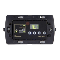
Explains the functions of the ON/OFF button, S button, and Arrow Up/Down buttons.
Describes the display segments, ambient temperature, and warning lights.
Details the infrared and internal temperature probes used by the panel.
How to set and display the desired ambient temperature for the unit.
Lists and briefly describes the available operating modes (Auto, Cool, Heat, etc.).
Explains how to select fan speed, including Auto and manual settings.
Details how the panel automatically selects cooling or heating to maintain the set temperature.
Describes the mode where only the fan operates without heating or cooling.
Explains the mode that adjusts set temperature based on parameter C50 for unattended operation.
Details the multi-phase cycle for dehumidifying the air, including fan and cooling operations.
Describes the mode where the unit operates exclusively in heating.
Describes the mode where the unit operates exclusively in cooling.
How to configure the fan to operate automatically based on ambient conditions.
How to manually select one of the four available fan speeds.
Details parameters CO1 and CO2 for setting max/min fan speeds in Auto Mode.
Commutes temperature measurement between Fahrenheit (°F) and Celsius (°C).
Controls fan automatic logic, adjusting speed based on Set Point proximity ('d' or 'U').
Determines if the fan continues or stops when the Set Point is reached ('ON' or 'OFF').
How to set up the Autostart function for resuming operation after a power loss.
Explains the HP alarm indication for high pressure switch activation and how to reset.
Describes the C.FL message indicating filter cleaning is due and how to reset the timer.
Explains messages like [nor] related to Dehumidify Mode conditions.
Details messages like [n.Pr] indicating powerboard setting or communication issues.
Interprets the [NA] display error, indicating an unavailable function due to parameter settings.
Sets the Maximum Inversion Limit (LSI) for heat-cool inversion in Auto Mode.
Sets the Minimum Inversion Limit (LII) for cool-heat inversion in Auto Mode.
Adjusts the Set Point in Unattended Mode for cooling or heating cycles.
Sets the duration (in minutes) for the Dehumidify Mode cycle within a 6-hour period.
Describes the various test sequences (t1-t5) for testing Fan Coil unit components.
Details test sequences for Compact/Split units, covering fan, pump, and compressor.
Explains how to display and interpret the timer parameters for running hours.
A table summarizing direct parameters like Set Point, Fan, Mode, Light, and Reset Timer.
Details indirect parameters such as Fan Max/Min Speed, °F/°C conversion, and Autostart.
Lists hidden parameters like Differential, PAR, and probe offsets, with their functions.
A flowchart illustrating the navigation and access to different parameter groups.
Describes the Vega MK II remote control device, its power source, and button functions.
Steps to diagnose and resolve issues when the panel display is not turning on.
Explains the meaning of the [nPr] display error and how to fix it via dip switch settings.
Interprets the [NA] display error, indicating an unavailable function due to parameter settings.
