"STUDIO" - HEAT RECOVERY UNIT
INSTALLATION AND OPERATING INSTRUCTIONS
S
AFETY NOTICE
It is important to read this Instruction Manual carefully before installing or using the product. Following
these instructions will ensure that your ventilation system is installed, commissioned and used properly
and continues to operate effectively. Vectaire will not be held responsible and will not accept liability
for any damage caused to persons or property through failure to follow the guidance provided in this
manual. It should always be available with the product for easy reference.
Your unit SHOULD NOT be switched off (except during maintenance). It is designed to run continuously.
If it is switched off indoor pollutant and moisture levels may increase.
Studio: 125mm spigot, for continuous ventilation
Max airflow 63 l/s
GENERAL INFORMATION
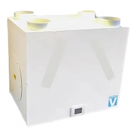
The Vectaire Studio heat recovery system provides mechanical ven-
tilation to bedrooms and bathrooms. It extracts stale, contaminated
air from bathrooms, replaces it with fresh air to the bedroom and
vents the stale air to the outside.
Heat is reclaimed from the extracted air and used, via a heat
exchanger, to warm the incoming fresh air. The extract and intake
airstreams are completely separate to avoid cross-contamination.
The system operates continuously and is designed not be switched
off, except for maintenance purposes.
During normal operation, the unit produces a low-volume airflow,
creating a comfortable, healthy environment, with minimum energy consumption.
If additional ventilation is required, (e.g. when a shower is in use), a boost facility is
included which increases the airflow rate. The boost can be operated automatically
or manually.
Installation of the unit is usually above a ceiling or in a loft space and is connected
to air vents via hidden ductwork.
Each unit is commissioned individually allowing its performance to be matched to the size of area to be ven-
tilated.
STANDARD FEATURES
1. Variable adjustment of low (trickle) and boost speeds for optimum setting at installation.
2. Adjustable overrun timer on boost setting - factory set to zero.
3. Adjustable delay-on timer, factory set to 2 minutes
4. Adjustable night-time boost inhibitor set to operate from 10.00 p.m to 6.00 a.m
5. Multiple choice of external devices for automatic or manual boost switching (e.g. light switch, remote
switch/pull cord, PIRFF passive infra-red*, DRH240 humidistat*, THM thermostat*.)
*Note : Contact Vectaire for supply of these items.
OPTIONAL ADDITIONAL FEATURE
BMS connections for remote motor shut-off.
Page 2
Incoming fresh air
Warmed fresh air
Extracted warm,
moist, stale air
Cooled outgoing
stale air
Studio
GENERAL SAFETY
PLEASE READ THESE INSTRUCTIONS FULLY, BEFORE ATTEMPTING ANY INSTALLATION
1. This product must not be used for any purpose other than that for which it was designed and shown
in this leaflet.
2. All packaging should be removed and the unit checked for damage. If any damage is found, contact
your supplier.
3. This product will normally be fitted into a loft or ceiling void.
In order to comply with Construction (Design & Management) Regulations, sufficient access for
safe maintenance (recommended on an annual basis), or removal following installation, MUST be
provided for this product. See dimensions above.
4. The unit must NOT be installed:
- where there is excessive oil or grease
- where there are hazardous gases, liquids or vapours that are flammable or corrosive
- in ambient temperatures above 50ºC or lower than 5ºC
- in humidity levels above 90% or in a wet environment
5. If any room from which air is extracted contains a fuel burning appliance, such as a central heating
boiler, then its flue must be of the sealed or balanced flue type, or allowance must be made for an
adequate supply of air into the room.
6. The mains supply voltage and power rating must comply with the details on the product rating label.
P
age 3
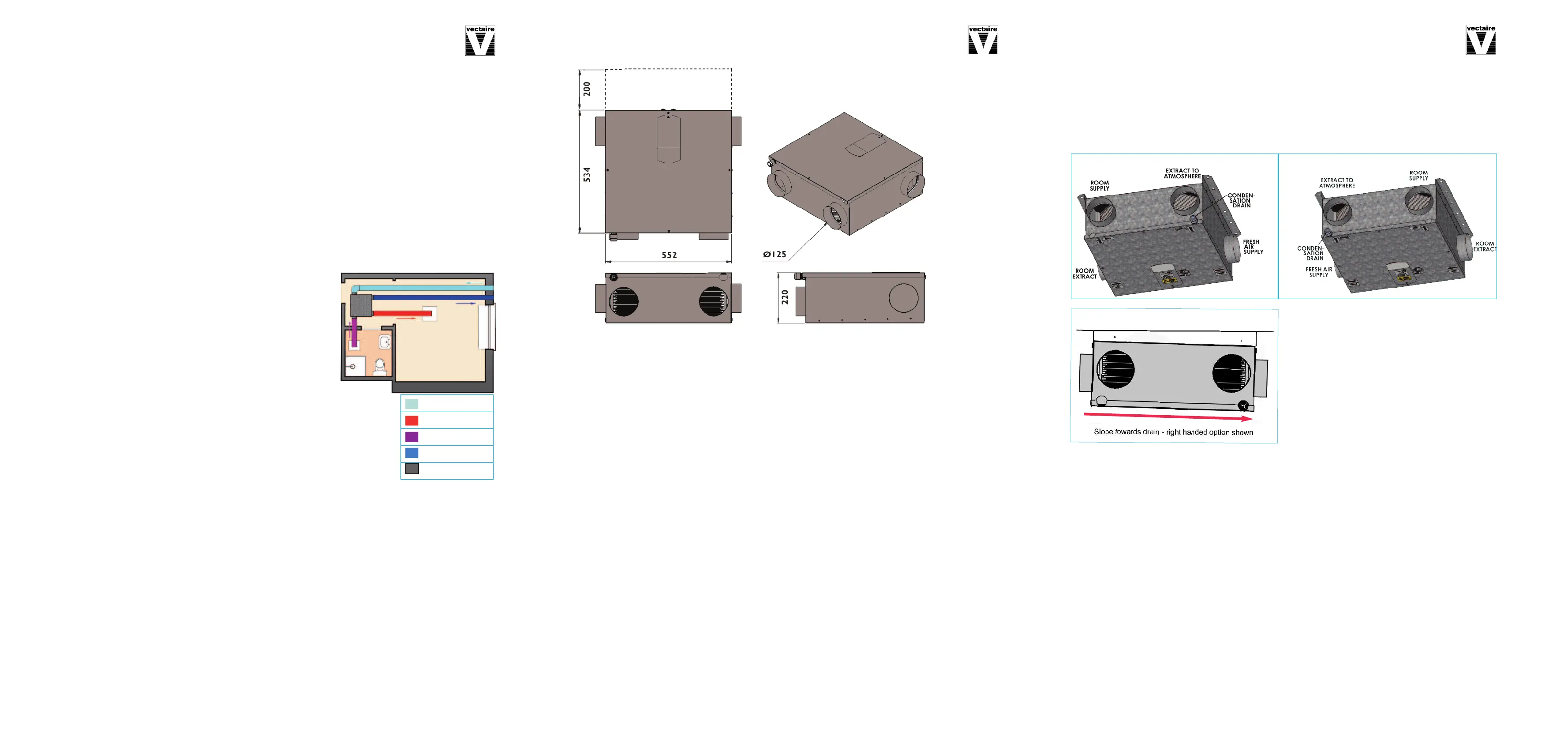
DIMENSIONS - mm
N.B a clearance of
a
t least 200 mm
s
hould be allowed
a
t the rear of the
unit in order to re-
p
lace filters. A
clearance of
220mm should be
allowed at bottom
of unit when in-
stalled for access
to the heat ex-
changer
*236mm with mounting bracket on drain side
I
NSTALLATION
Installation must be carried out by a suitably qualified person and must comply with all current building
regulations and electrical installation regulations.
Mounting the unit
B
efore choosing the position for mounting, it is important to take into consideration the ductwork routes
and condensate drain route. The four spigots on the unit are marked for the four unique connections. The
unit can be supplied left or right-handed in order to match the required duct routes more easily. (Factory
option only.)
It is also essential that adequate access to the
product is provided for maintenance or removal
after installation. The entire access panel needs to
be removed for maintenance.
The unit is intended to be suspended from a ceiling
or similar fixture. Two identical fixing brackets are
supplied with each unit. It is important that the unit
is attached to ithese brackets so that there is a slope
down towards the condensation drain connector of
the product. When correctly fitted, the brackets will
provide a drop of approximately 15mm at the lower
end.
Duct and Duct Connections (refer to design drawing)
1. 4 x 125mm nominal diameter spigots are provided for the connection of ducting. These are clearly
marked for correct connection of the supply and exhaust ducts.
2. Where ducting is installed in an unheated space, all of the ducts should be insulated. Where ducting is
installed in a heated space, only the cold ducts should be insulated. i.e. the supply duct from outside and
the extract duct from the unit to the outside.
3. The duct layout must be designed to suit the requirements of the ventilation/heat recovery system and
building layout. If the ducting passes through a fire wall/barrier, suitable fire dampers must be
installed.
4. Where rigid duct is used (preferable), it should be installed using the least number of fittings to min
imise air flow resistance. Where possible, final connection to the grilles and unit should be made with
a flexible connection.
5. Where flexible ducts are used, ensure that:
- duct runs are kept as short as possible
- the duct is stretched so that it is smooth and straight
- where bends are necessary, they have large radii (ie avoid sharp bends)
- the duct is not crushed if in a restricted area
Note: Whenever the unit is installed in close proximity to a bedroom or other habitable space, we recom-
mend that sound attenuation is provided within the duct runs between the rooms and the unit. A length of
1 metre of flexible acoustic ducting will be sufficient in most circumstances, but reference should be made
to the sound data provided for this product
Page 4
Dia
gra
m s
ho
wing slo
pe to
wards
dra
in
Studio - option 1 (right hand drain)
Studio - option 2 (left hand drain)
 Loading...