EasyManua.ls Logo

Vector 4 - Page 142

Vector 4
227 pages
Print Icon
To Next Page IconTo Next Page
To Previous Page IconTo Previous Page
Loading...
VECTOR
4
TECHNICAL
INFORMATION
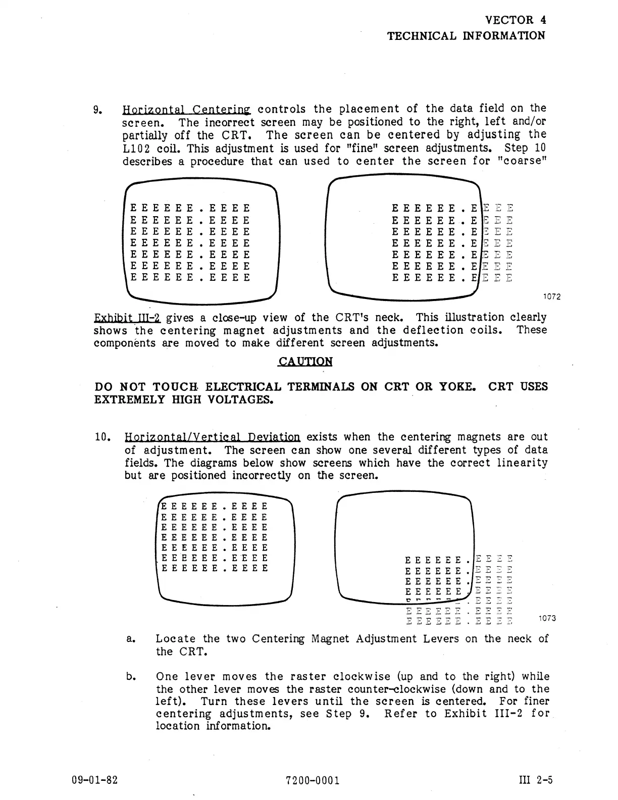
9.
Horizontal
Centering
controls
the
placement
of
the
data
field on
the
screen.
The
ineorrect
screen
may
be
positioned
to
the
right,
left
and/or
partially
off
the
CRT.
The
screen
can
be
centered
by
adjusting
the
L102
coil.
This
adjustment
is
used
for
"fine"
screen
adjustments.
Step
10
describes
a
procedure
that
can
used
to
center
the
screen
for
"coarse"
B
fl
¥
g
EEEEE
.EEEE
EEEEEE
.
ElE
=X
EEEEEE
.EEEE
EEEEEE
.Ef
&
X
EEEEEE
.EEEE
EEEEEE
.EJE
&I
EEEEEE
.EEEE
EEEEEE
.EfE
E
X
EEEEEE
.EEEE
EEEEEE.E[E
ZE
EEEEEE
.EEEE
EEEEEE
.
EIf
£X
EEEEEE
.EEEE
EEEEEE.
EE
EZ
.
1072
Exhibit
III-2
gives
a
close-up
view
of
the
CRT's
neck.
This
illustration
clearly
shows
the
centering
magnet
adjustments
and
the
deflection
coils.
These
components
are
moved
to
make
different
screen
adjustments.
CAUTION
DO
NOT
TOUCH
ELECTRICAL
TERMINALS
ON
CRT
OR
YOKE.
CRT
USES
EXTREMELY
HIGH
VOLTAGES.
|
10,
exists
when
the
centering
magnets
are
out
of
adjustment.
The
screen
can
show
one
several
different
types
of
data
fields.
The
diagrams
below
show
screens
which
have
the
correct
linearity
but
are
positioned
incorrectly
on
the
screen.
|
EEEEEE.EEEE
EEEEEE.EEEE
EEEEEE.EEEE
EEEEEE.EEEE
EEEEEE.EEEE
EEEEEE.EEEE
EEEEEE.|[E=zz=
EEEEEE.EEEE
EEEEEE.IFEZZE
EEEEEE
JZEZIZ
EEEEEE
JEZ
=
&
Cr
oS’
T
LT
a.
Locate
the
two
Centering
Magnet
Adjustment
Levers
on
the
neck
of
the
CRT.
b.
One
lever
moves
the
raster
clockwise
(up
and
to
the
right)
while
the
other
lever
moves
the
raster
counter-clockwise
(down
and
to
the
left).
Turn
these
levers
until
the
scereen
is
centered.
For
finer
centering
adjustments,
see
Step
9.
Refer
to
Exhibit
III-2
for
location
information.
09-01-82
7200-0001
I
2-5